
Magnetic liquid sealing device

A magnetic liquid and sealing device technology, applied in the direction of engine sealing, engine components, mechanical equipment, etc., can solve the problems of magnetic liquid loss, affecting sealing performance, small sealing gap, etc., and achieve the effect of not easy adsorption and uniform distribution

Active Publication Date: 2021-04-30
TSINGHUA UNIV
View PDF5 Cites 0 Cited by
  • Summary
  • Abstract
  • Description
  • Claims
  • Application Information

AI Technical Summary

Problems solved by technology

However, due to the small sealing gap and the response characteristics of the magnetic liquid to the magnetic field, it is a difficult problem to fill the magnetic liquid into the sealing gap uniformly and effectively to form a stable and ideal magnetic liquid seal.
In addition, the magnetic liquid is easily absorbed by the permanent magnet during the filling process, resulting in the loss of the magnetic liquid and affecting the sealing performance

Method used


Image

  • Magnetic liquid sealing device
  • Magnetic liquid sealing device
  • Magnetic liquid sealing device

Examples


Embodiment 1

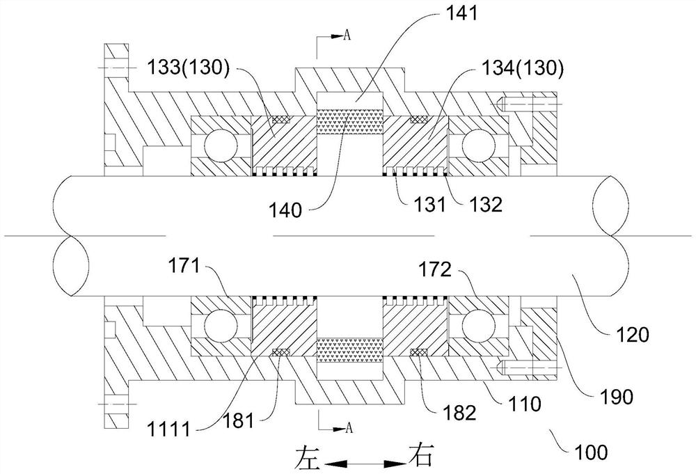
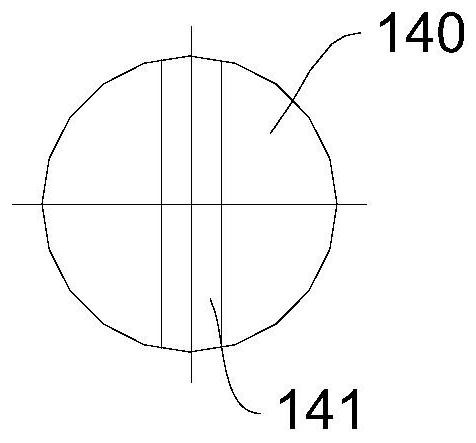
[0046]Such asfigure 1 As shown, the magnetic liquid sealing device 100 in the present embodiment includes a shaft case 110, a rotating shaft 120, a first pole shoe 133, a second pole shore 134, and a permanent magnet group (first permanent magnet group). The first permanent magnet group includes a plurality of permanent magnets 140, and several permanent magnets 140 are arranged around the shaft 120 along the circumferential direction of the shaft 120. In this embodiment, the permanent magnet 140 is a cylindrical shape, the axial direction is the same as the axial direction of the rotating shaft 120. It will be appreciated that in other embodiments, the permanent magnet 140 can be other columnar structures.

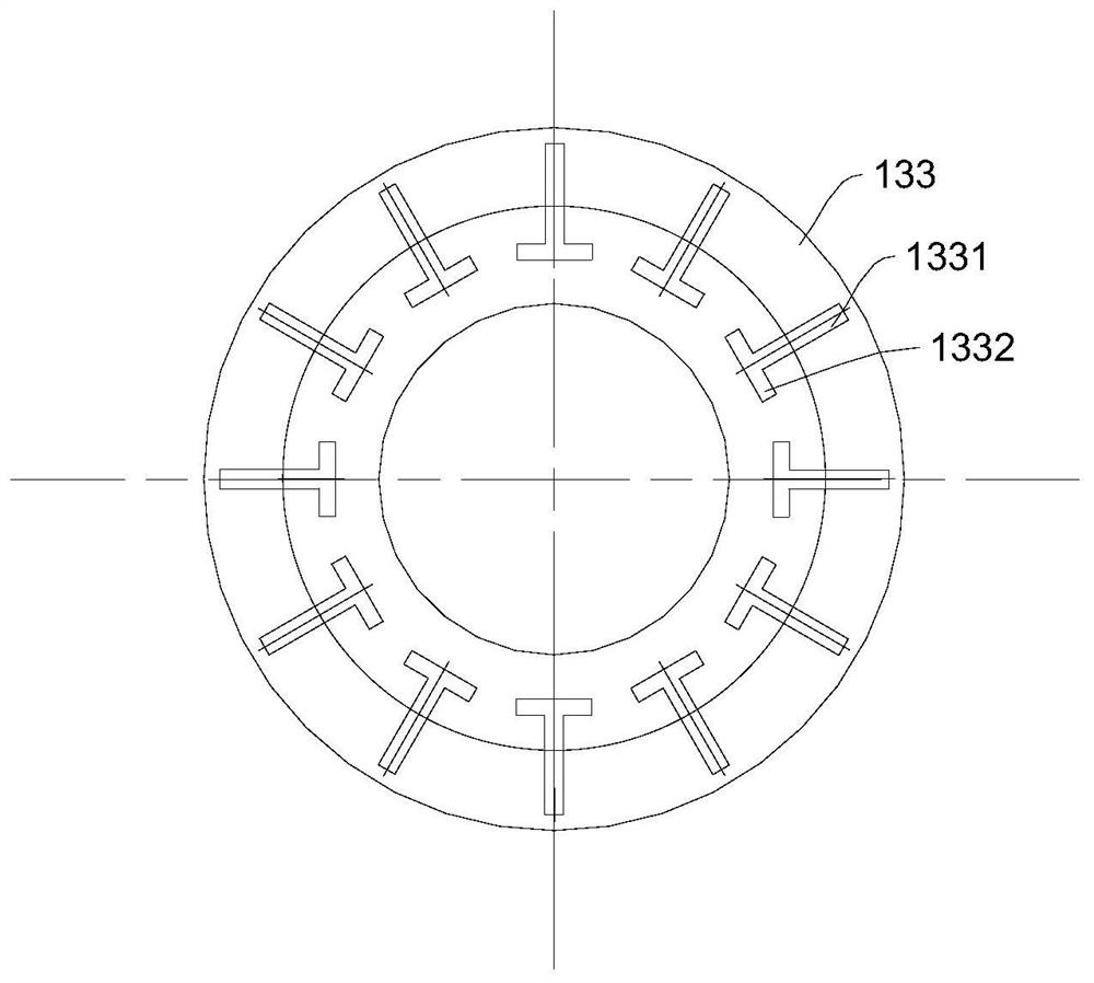
[0047]The first pole shoe 133 and the second pole shoe 134 are all set to the shaft 120, and the outer circumferential surface is connected to the peripheral wall surface 1111 of the chamber 111 to be connected to the shaper shell 110. The first permanent magnet group is located b...

Embodiment 2

[0065]The structure of the magnetic liquid sealing device in this embodiment is basically the same as that of the Example, and will be described herein. Different from the circumferential wall surface 1111 formed a plurality of avoidance grooves 112, the plurality of avoidance grooves 112 corresponds to a plurality of permanent magnets 140 in the first permanent magnet group, and the avoidance groove 112 and the diameter of the permanent magnet 140 corresponding to the rotation shaft 120. On the other hand, that is, at least a portion of the permanent magnet 140 can be located within the avoidance groove 112 corresponding thereto. It will be appreciated that the plurality of avoidance grooves 112 are arranged around the circumferential direction of the rotating shaft 120 on the circumferential wall surface 1111. Alternatively, in other embodiments, a plurality of avoidance grooves 112 around the circumferential arrangement around the shaft 120 are formed, each of which corresponds t...

Embodiment 3

[0068]The structure of the magnetic liquid sealing device in this embodiment is basically the same as that of the Example, and will be described herein. Different, such asFigure 4 As shown, the shaft case 110 in the present embodiment includes a first sub-axle housing 113 and a second sub-axle shell 114. The first sub-axle housing 113 and the second sub-axle housing 114 are arranged in the axial direction of the shaft 120 and detachably interconnected. The first sub-axle housing 113 and the second sub-axle housing 114 collectively define the chamber 111 and the avoidance tank 112. Alternatively, the first sub-axle housing 113 and the second sub-axle case 114 are connected by a connection bolt 160.

[0069]The first pole shoe 133 is located within the subcarcies formed by the first sub-axis casing 113, and the second pole shoe 134 is located in the sub-chamber formed by the second sub-axle housing 114. The left end of the permanent magnet 140 extends into the first sub-axle case 113, an...


PUM


Abstract

The embodiment of the invention provides a magnetic liquid sealing device and an assembly method thereof. According to the magnetic liquid sealing device provided by the embodiment of the invention, an avoiding groove for avoiding a permanent magnet is formed in the peripheral wall surface of a cavity, and the permanent magnet is located in the avoiding groove, so that the permanent magnet can be far away from pole teeth; therefore, the relative distance between the permanent magnet and the pole teeth can be conveniently adjusted in the assembly process, so that the magnetic liquid can be uniformly and effectively distributed in a sealing gap; and the magnetic liquid can be prevented from being mistakenly adsorbed onto the permanent magnet. The magnetic liquid sealing device provided by the embodiment of the invention has the advantages that the magnetic liquid is uniformly distributed and is not easily adsorbed by the permanent magnet.

Description

Technical field[0001]The present invention relates to the field of sealing devices, and more particularly to a magnetic liquid sealing device.Background technique[0002]The magnetic liquid sealing device has the advantages of zero leakage, no wear, long life, and simple structure, and is used in more and more industries. However, due to the small sealing clearance, the magnetic liquid responds to the magnetic field, the magnetic liquid is uniform, effectively fill into the sealing gap to form a stable and ideal magnetic liquid seal is a problem. Further, the magnetic liquid is easily adsorbed by the permanent magnet during the filling process, causing the loss of magnetic liquid, affecting the sealing performance.Inventive content[0003]The present invention is intended to solve one of the technical problems in the relevant techniques at least to some extent. To this end, embodiments of the present invention proposes a magnetic liquid sealing device having a uniform magnetic liquid di...

Claims


Application Information

Patent Timeline
Patent Type & Authority Applications(China)
IPC IPC(8): F16J15/43
CPCF16J15/43
Inventor 李德才赵云翔杨晟
Owner TSINGHUA UNIV
Learn More