Screw locking torque detection mechanism

A torque detection and screw locking technology, applied in the direction of torque/torsional force measurement, metal processing, metal processing equipment, etc. during tightening, which can solve the problems of locking the motor shaft, difficult mechanism design, and low work efficiency.

Pending Publication Date: 2021-04-30
JIANGSU COWAIN AUTOMATION TECH
View PDF0 Cites 0 Cited by
  • Summary
  • Abstract
  • Description
  • Claims
  • Application Information

AI Technical Summary

Problems solved by technology

[0002] The connection between the motor housing and the cover plate requires screws to be fastened, and in order to improve the firmness, some motor housings need up to 7 screws to be fixed. The work efficiency of manual screw tightening is low, and electric screwdrivers are often used for tightening. solid
[0003] When the electric screwdriver fastens the screws on the motor casing, the motor casing needs to be rotated intermittently, and the screws of multiple holes are tightened in sequence. Generally, an electric indexing plate can be used. However, on the motor casing In the process of fastening the cover plate, in order to avoid the problem of locking the central axis of the motor, it is necessary to carry out the rotation drive and torque detection of the central axis of the motor to ensure that a certain force value is maintained during the rotation process, which brings great difficulties to the design of the whole mechanism. difficulty

Method used


Image

  • Screw locking torque detection mechanism
  • Screw locking torque detection mechanism
  • Screw locking torque detection mechanism

Examples


Embodiment Construction

[0021] The technical solutions in the embodiments of the present invention will be described clearly and completely below, obviously, the described embodiments are only some of the embodiments of the present invention, but not all of the embodiments. Based on the embodiments of the present invention, all other embodiments obtained by persons of ordinary skill in the art without making creative efforts belong to the protection scope of the present invention.

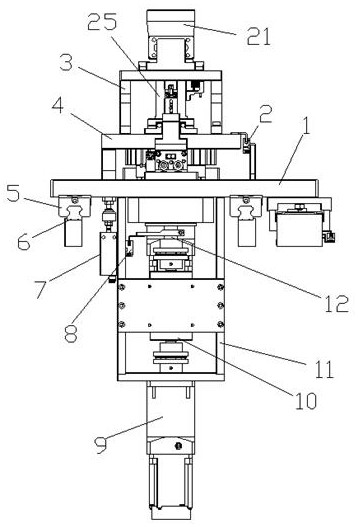
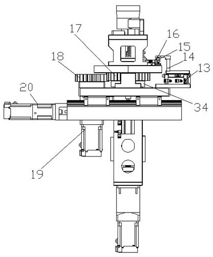
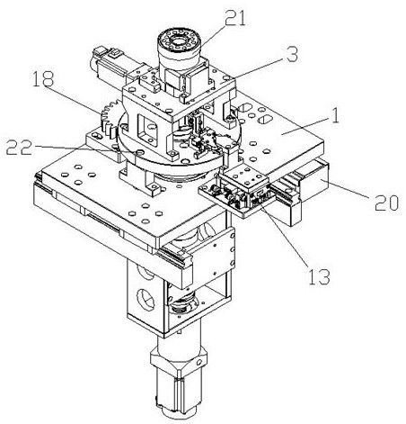
[0022] see Figure 1~Figure 4 , the embodiment of the present invention includes:

[0023] Such as figure 1 The lock screw torque detection mechanism shown includes: a moving seat 1, a shaft sleeve 25, a motor housing carrier 3, a turntable 4, a servo motor 9 for measuring torque, a dynamic torque sensor 10, a transmission shaft 12 for measuring torque and a positioning key Control assembly, the slide rail 6 is arranged under the moving seat 1, and the slider 5 on the slide rail 6 is arranged at the bottom of the moving...


PUM


Abstract

The invention discloses a screw locking torque detection mechanism, which comprises a moving seat, a shaft sleeve, a motor shell carrier, a turntable, a servo motor for measuring torque, a dynamic torque sensor, a transmission shaft for measuring torque and a positioning key control assembly, and is characterized in that the turntable is horizontally arranged on the moving seat, and the motor shell carrier is arranged on the turntable; the shaft sleeve is located below the motor shell carrier, the outer circle of the shaft sleeve is provided with a positioning key insertion hole extending to a middle hole in the radial direction, displacement control over the positioning key in the positioning key insertion hole is conducted through the positioning key control assembly, and the transmission shaft for measuring torque is arranged at the bottom of the shaft sleeve. The dynamic torsion sensor is connected in series between the transmission shaft for measuring the torque and the servo motor for measuring the torque. By means of the mode, the screw locking torque detection mechanism drives the motor shell to rotate intermittently and drives the motor middle shaft to rotate, torque detection is conducted, the structure is compact, and the working efficiency is high.

Description

technical field [0001] The invention relates to the field of industrial automation manufacturing and assembly, in particular to a locking screw torque detection mechanism. Background technique [0002] The connection between the motor housing and the cover plate requires screws to be fastened, and in order to improve the firmness, some motor housings need up to 7 screws to be fixed. The work efficiency of manual screw tightening is low, and electric screwdrivers are often used for tightening. solid. [0003] When the electric screwdriver fastens the screws on the motor casing, the motor casing needs to be rotated intermittently, and the screws of multiple holes are tightened in sequence. Generally, an electric indexing plate can be used. However, on the motor casing In the process of fastening the cover plate, in order to avoid the problem of locking the central axis of the motor, it is necessary to carry out the rotation drive and torque detection of the central axis of th...

Claims


Application Information

Patent Timeline
Patent Type & Authority Applications(China)
IPC IPC(8): G01L5/24B23P19/06
CPCB23P19/06G01L5/24
Inventor 韩鹏李伟
Owner JIANGSU COWAIN AUTOMATION TECH
Why Eureka
Try Eureka