Metal thin net punching cutter structure

A technology of thin metal and cutting tools, which is applied in the direction of manufacturing tools, metal processing equipment, storage devices, etc., can solve the problems of increased distance, wrinkling of thin metal mesh 2, poor quality of thin metal mesh 2, etc., and achieve the best quality Effect

Pending Publication Date: 2021-05-04
JUN EN ENTERPRISE CORP +1
View PDF8 Cites 0 Cited by
  • Summary
  • Abstract
  • Description
  • Claims
  • Application Information

AI Technical Summary

Problems solved by technology

[0003] see figure 1 and figure 2 The cutter set 1 of the expanded mesh machine shown is mainly intended to punch the thick metal mesh. Due to the high rigidity of the thick metal mesh itself, when the upper knife seat 11 and the upper cutter 12 move downward, The upper knife 12 is supported by the upper knife seat 11, so that the upper knife 12 will not move backward, and the upper knife 12 will not be separated from the upper knife seat 11 due to excessive punching force. 1 If it is desired to die-cut the thin metal mesh 2 with better ductility, when the thin metal mesh 2 is conveyed to the gap 16 between the pressing plate 15 and the upper cutter 12 through the conveying path 17, the gap 16 at the The thin metal mesh 2 is easily wrinkled without being pressed and set by the pressing plate 15, and then when the upper cutter 12 punches the bottom cutter 14, it is easy to make the mesh of the thin metal mesh 2 uneven.
[0004] Since the edge of the upper knife 12 of the upper knife seat 11 is directly punching the bottom knife 14, it is found that the edge of the upper knife 12 is easily damaged and blunt after punching, so that the upper knife 12 must be disassembled. After the edge 121 of the upper cutter 12 is ground each time, in addition to reassembling the upper cutter 12 on the first placement area 111 below the upper knife seat 11 side, the upper The edge 121 of the cutter 12 is worn out due to punching for a long time, and the edge 121 of the cutter is ground again, so that the gap 16 between the edge 121 of the upper cutter 12 and the pressing plate 15 will increase again, causing the gap 16 at the gap 16 position. The thin metal mesh 2 is wrinkled, and the distance between the knife edge 121 of the upper knife 12 and the knife edge 141 of the bottom knife 14 will also become larger, and the distance between the bottom knife 14 and the upper knife 12 must be readjusted. The gap 16, so as to affect the change of the overall assembly position of the upper knife seat 11, and fail to achieve a consistent processing flow, so the quality of the thin metal mesh 2 produced is not good

Method used


Image

  • Metal thin net punching cutter structure
  • Metal thin net punching cutter structure
  • Metal thin net punching cutter structure

Examples


Embodiment Construction

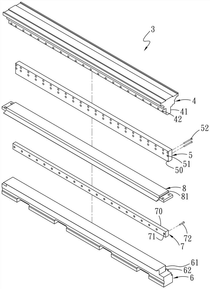
[0060] see image 3 , 4 and Figure 5 , 6 As shown, the present invention proposes a thin metal mesh punching cutter structure, which is used for punching thin metal mesh 9 . The thin metal punching cutter structure 3 includes an upper cutter seat 4 , an upper cutter 5 , a bottom cutter seat 6 , a bottom cutter 7 , and a pressing plate 8 . in,

[0061] There is a first placement area 41 below one side of the upper knife seat 4 , and a plurality of first screw holes 42 are distributed on the inner side of the first placement area 41 .

[0062] The upper knife 5 is fixed on the first placement area 41 below the upper knife seat 4 side, and a plurality of penetrating holes corresponding to the first screw holes 42 are distributed near the top of the upper knife 5. The holes 51 are respectively penetrated into the first screw holes 42 of the upper tool seat 4 from the through holes 51 of the upper tool 5 by using a plurality of first screw members 52 to form screw fastening. ...


PUM


Abstract

The invention discloses a metal thin net punching cutter structure which comprises an upper cutter holder, an upper cutter arranged below one side of the upper cutter holder, a bottom cutter holder corresponding to a cutter edge of the upper cutter, a bottom cutter arranged above one side of the bottom cutter holder, and a pressing plate arranged on the bottom cutter holder and the bottom cutter, one side of the pressing plate abuts against the upper cutter, so that no gap exists between the pressing plate and the upper cutter, when the bottom cutter is punched by the upper cutter and a metal thin net is punched, meshes of the metal thin net can be equal, wrinkles cannot be generated, meanwhile, when the cutter edge of the upper cutter is abraded in the punching process, the upper cutter is disassembled, the cutter edge of the upper cutter is assembled to the upper cutter holder after being ground, and the metal thin net is prevented from being wrinkled in the punching process.

Description

technical field [0001] The invention relates to a cutter structure, in particular to a thin metal mesh punching cutter structure which prevents wrinkles from being produced in the punching process of the thin metal mesh and enables the mesh holes of the thin metal mesh to be uniform after punching . Background technique [0002] The knife set 1 of the general expansion net machine in the stamping process, please refer to figure 1 and figure 2 As shown, the knife set 1 includes an upper knife seat 11 , an upper knife 12 , a bottom knife seat 13 , a bottom knife 14 , and a pressing plate 15 . There is a first placement area 111 below one side of the upper knife seat 11 , and a plurality of holes 112 are provided on the upper knife seat 11 . The upper cutter 12 is fixed on the first placement area 111 at the bottom front end of the upper cutter holder 11. The upper cutter 12 is provided with a plurality of screw holes 120 corresponding to the holes 112, and utilizes a plura...

Claims


Application Information

Patent Timeline
Patent Type & Authority Applications(China)
IPC IPC(8): B21D31/04B21D43/00
CPCB21D31/04B21D43/003
Inventor 王银福
Owner JUN EN ENTERPRISE CORP
Why Eureka
Try Eureka