Bridge guardrail

A technology for guardrails and bridges, applied in bridges, bridge parts, bridge construction, etc., can solve the problems of guardrails with little protection, too simple functions, and lack of safety

Active Publication Date: 2021-05-04
海南路桥工程有限公司
View PDF5 Cites 0 Cited by
  • Summary
  • Abstract
  • Description
  • Claims
  • Application Information

AI Technical Summary

Problems solved by technology

[0004] Aiming at the deficiencies of the prior art, the present invention provides a bridge guardrail, which solves the problem that the bridge guardrail lacks safety on the basis of satisfy...

Method used


Image

  • Bridge guardrail
  • Bridge guardrail
  • Bridge guardrail

Examples


Embodiment 1

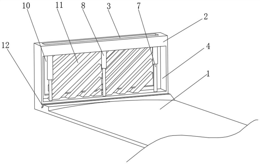
[0030] see figure 1 , the present invention provides a technical solution: a bridge guardrail, including a bridge base surface 1, the outer surface of the bridge base surface 1 is fixedly connected with a protective pile 2, the top of the protective pile 2 is provided with a greening groove 3, and the outer surface of the protective pile 2 On the surface and below the greening groove 3, there is a through groove 4, the top and bottom of the inner surface of the through groove 4 are provided with a curved groove 5, and the inner surface of the curved groove 5 is provided with an elastic mechanism 6, two curved grooves 5 The opposite sides are evenly slidably connected with a curved rod 7, the outer surface of the curved rod 7 is fixedly connected with an anti-collision mechanism 8, and the outer surface of the curved rod 7 is movably connected with the inner surface of the curved groove 5. The buffer mechanism 9, the inner surface of the through groove 4 and is located directly...

Embodiment 2

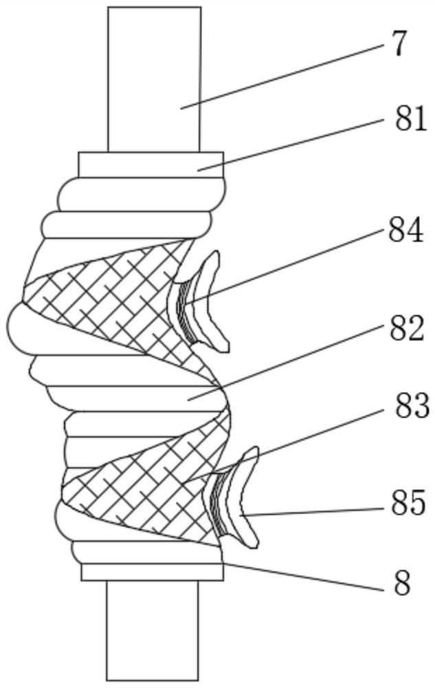
[0032] see figure 2, the present invention provides a technical solution: the anti-collision mechanism 8 includes a shock absorbing sleeve 81, the outer surface of the shock absorbing sleeve 81 is fixedly connected with the outer surface of the curved rod 7, and the outer surface of the shock absorbing sleeve 81 is wound and connected with The anti-collision rubber strip 82, the outer surface of the shock-absorbing sleeve 81 and the top and bottom of the anti-collision rubber strip 82 are wound and connected with a shock-absorbing pad 83, and the outer surface of the shock-absorbing pad 83 is fixedly connected with a spring leaf 84, and the spring leaf The outer surface of 84 is fixedly connected with a sliding piece 85, and the outer surface of the sliding piece 85 is a curved surface. By wrapping the anti-collision rubber strip 82 and the shock pad 83 on the outside of the shock-absorbing sleeve 81 , the impact force of the vehicle can be dispersed after the outside of the ...

Embodiment 3

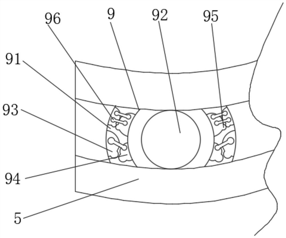
[0034] see image 3 , the present invention provides a technical solution: the buffer mechanism 9 includes a buffer casing 91, the outer surface of the buffer casing 91 is movably connected with the inner surface of the curved groove 5, and a circular groove 92 is provided at the center of the buffer casing 91. The inner surface of the groove 92 is movably connected with the outer surface of the curved rod 7 , and the inner surface of the buffer casing 91 is evenly and fixedly connected with a first buffer hemisphere 93 . When the curved rod 7 is subjected to an impact force, the fixed connection can be changed to shake left and right in a small range, which gives the curved rod 7 the effect of buffering force, and the first buffer hemisphere 93 and the second buffer hemisphere 94 arranged inside collide with each other , can avoid the curved rod 7 from shaking too much, and has a limited effect, which improves the flexibility and service life of the protective pile 2 internal...


PUM


Abstract

The invention discloses a bridge guardrail, and relates to the technical field of bridges. The bridge guardrail comprises a bridge foundation surface; the outer surface of the bridge foundation surface is fixedly connected with protection piles; a greening groove is formed in the top of each protection pile, a through groove is formed in the outer surface of each protection pile and located below the corresponding greening groove, curved grooves are formed in the top and the bottom of the inner surface of each through groove, and elastic mechanisms are arranged on the inner surfaces of the curved grooves; and curved rods are uniformly connected between the opposite sides of the two curved grooves in a sliding manner. Anti-collision mechanisms, buffering mechanisms and the elastic mechanisms are arranged between the protection piles, the problem that the protection piles are single in function is solved, when a vehicle is collided, and the protection piles can have certain buffering force when receiving impact force generated by collision; rotatable parts are arranged in the protection piles, the rotation effect is generated when the protection piles make contact with the vehicle, the effect of dispersing impact force is achieved to a certain extent, damage to the protective piles caused by part of impact is relieved, and the safety of the bridge guardrail effect is improved.

Description

technical field [0001] The invention relates to the technical field of bridges, in particular to a bridge guardrail. Background technique [0002] Bridges generally refer to structures erected on rivers, lakes and seas to allow vehicles and pedestrians to pass smoothly. In order to adapt to the modern high-speed development of the transportation industry, bridges are also extended to buildings that cross mountain streams, poor geology or meet other transportation needs to make traffic more convenient. A bridge is generally composed of a superstructure, a substructure, a support and ancillary structures. The superstructure is also called a bridge span structure, which is the main structure for crossing obstacles; the substructure includes abutments, piers and foundations; Or the force transmission device installed at the supporting place of the bridge abutment; the auxiliary structures refer to the bridge head board, conical slope protection, bank protection, diversion works...

Claims


Application Information

Patent Timeline
IPC IPC(8): E01D19/10E01F15/04E01F15/00
CPCE01D19/103E01F15/0484E01F15/00
Inventor 腾娟
Owner 海南路桥工程有限公司
Why Eureka
Try Eureka