Detachable combined type valve structure

A combination and valve technology, applied in the direction of the valve shell structure, valve details, valve device, etc., can solve the problems of difficult disassembly, high maintenance cost, waste of resources, etc., and achieve simple installation and disassembly, stable sealing, and convenient replacement Effect

Inactive Publication Date: 2021-05-04
ZHEJIANG IND & TRADE VACATIONAL COLLEGE
View PDF0 Cites 0 Cited by
  • Summary
  • Abstract
  • Description
  • Claims
  • Application Information

AI Technical Summary

Problems solved by technology

[0002] Valves are pipeline accessories used to open and close pipelines, control flow direction, adjust and control the parameters (temperature, pressure and flow) of the conveying medium. There are quite a variety of varieties and specifications, but they are usually divided into integral and combined types according to the structure type. , the integral valve structure is simple and the production cost is low, but it is troublesome to disassemble in an orderly manner when the parts inside the valve are damaged, it is not easy to replace them separately, the maintenance cost is high, and the sealing of the welding part is also difficult to guarantee, so it needs to be replaced as a whole, which is wasteful Resources; Common combined valves are usually integrated in one structure during use, and the concave-convex surface is usually used in the connection process to make the structure reliable. When the valve needs maintenance, the combined valve is removed as a whole, and then the combined valve When the valve is connected to a rigid pipeline, the valve that has been connected will not be easy to disassemble because the valve is a rigid part, and after repeated disassembly and assembly, the gap between the two nozzles that the valve needs to be connected will be damaged. After the valve is installed, it is difficult to ensure the sealing of the connection between the valve and the pipeline, which will affect the use

Method used


Image

  • Detachable combined type valve structure
  • Detachable combined type valve structure
  • Detachable combined type valve structure

Examples


Embodiment Construction

[0021] The following will clearly and completely describe the technical solutions in the embodiments of the present invention with reference to the accompanying drawings in the embodiments of the present invention. Obviously, the described embodiments are only some, not all, embodiments of the present invention. Based on the embodiments of the present invention, all other embodiments obtained by persons of ordinary skill in the art without making creative efforts belong to the protection scope of the present invention.

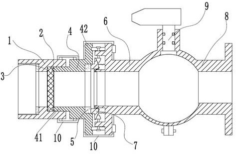
[0022] refer to Figure 1 to Figure 4 To further explain this application, such as figure 1 A detachable combined valve structure is shown, including a connecting cylinder 1 that can be fixedly connected to the flow pipe, a filter screen 2 placed in the connecting cylinder 1, inserted in the connecting cylinder 1 and pressed against The pressure sleeve 4 on the filter screen 2, the combined first valve body half-shell 6 and the second valve body half-shell 8,...


PUM


Abstract

The invention discloses a detachable combined type valve structure. The detachable combined type valve structure comprises a connecting cylinder, a filter screen placed in the connecting cylinder, a pressing sleeve which is inserted into the connecting cylinder and abuts against the filter screen, a first valve body half shell and a second valve body half shell which are combined together, a valve element body limited between the first valve body half shell and the second valve body half shell, and an adjusting locking mechanism, wherein a valve body flange plate of the first valve body half shell is provided with a connecting pipeline communicating with the valve cavity, the adjusting and locking mechanism comprises a floating sliding sleeve arranged on the connecting pipeline in a sleeving mode, and a plurality of elastic reset pieces are connected between the floating sliding sleeve and the valve body flange plate; a floating sliding sleeve drive mechanism arranged on the valve body flange plate is used for driving the floating sliding sleeve to be away from the valve body flange plate so that the end part of the floating sliding sleeve can be inserted into a counter bore of the pressing sleeve, a sealing gasket is arranged between the pressing sleeve and the floating sliding sleeve, and a sealing piece is arranged between the floating sliding sleeve and the connecting pipeline. In a using process, parts are convenient to disassemble and replace, and the valve body and the sealing performance cannot be damaged.

Description

technical field [0001] The invention relates to the field of valves, in particular to a detachable combined valve structure. Background technique [0002] Valves are pipeline accessories used to open and close pipelines, control flow direction, adjust and control the parameters (temperature, pressure and flow) of the conveying medium. There are quite a variety of varieties and specifications, but they are usually divided into integral and combined types according to the structure type. , the integral valve structure is simple and the production cost is low, but it is troublesome to disassemble in an orderly manner when the parts inside the valve are damaged, it is not easy to replace them separately, the maintenance cost is high, and the sealing of the welding part is also difficult to guarantee, so it needs to be replaced as a whole, which is wasteful Resources; Common combined valves are usually integrated in one structure during use, and the concave-convex surface is usua...

Claims


Application Information

Patent Timeline
IPC IPC(8): F16K27/00F16K51/00F16L23/032F16L23/024F16L23/18B01D35/04
CPCB01D35/04F16K27/00F16K51/00F16L23/024F16L23/032F16L23/18
Inventor 王坤金克雨尚玉来林继兴童先郝汀魏爱平孔祥威
Owner ZHEJIANG IND & TRADE VACATIONAL COLLEGE
Why Eureka
Try Eureka