High-safety power line repair tower lifting device

A lifting device and safety technology, which is applied in the field of electric power emergency repair tower lifting device, can solve the problems of poor flexibility, large limitations of electric power repair work, unfavorable good adjustment, etc., and achieve the effect of convenient and flexible use

Pending Publication Date: 2021-05-07
张清玲
View PDF9 Cites 1 Cited by
  • Summary
  • Abstract
  • Description
  • Claims
  • Application Information

AI Technical Summary

Problems solved by technology

In order to ensure the emergency repair work, each grassroots level is equipped with emergency repair vehicles, but the current electric emergency repair device has poor flexibility in use, which is not conducive to good adjustment by personnel, which makes the electric emergency repair work more limited

Method used


Image

  • High-safety power line repair tower lifting device
  • High-safety power line repair tower lifting device
  • High-safety power line repair tower lifting device

Examples


Embodiment 1

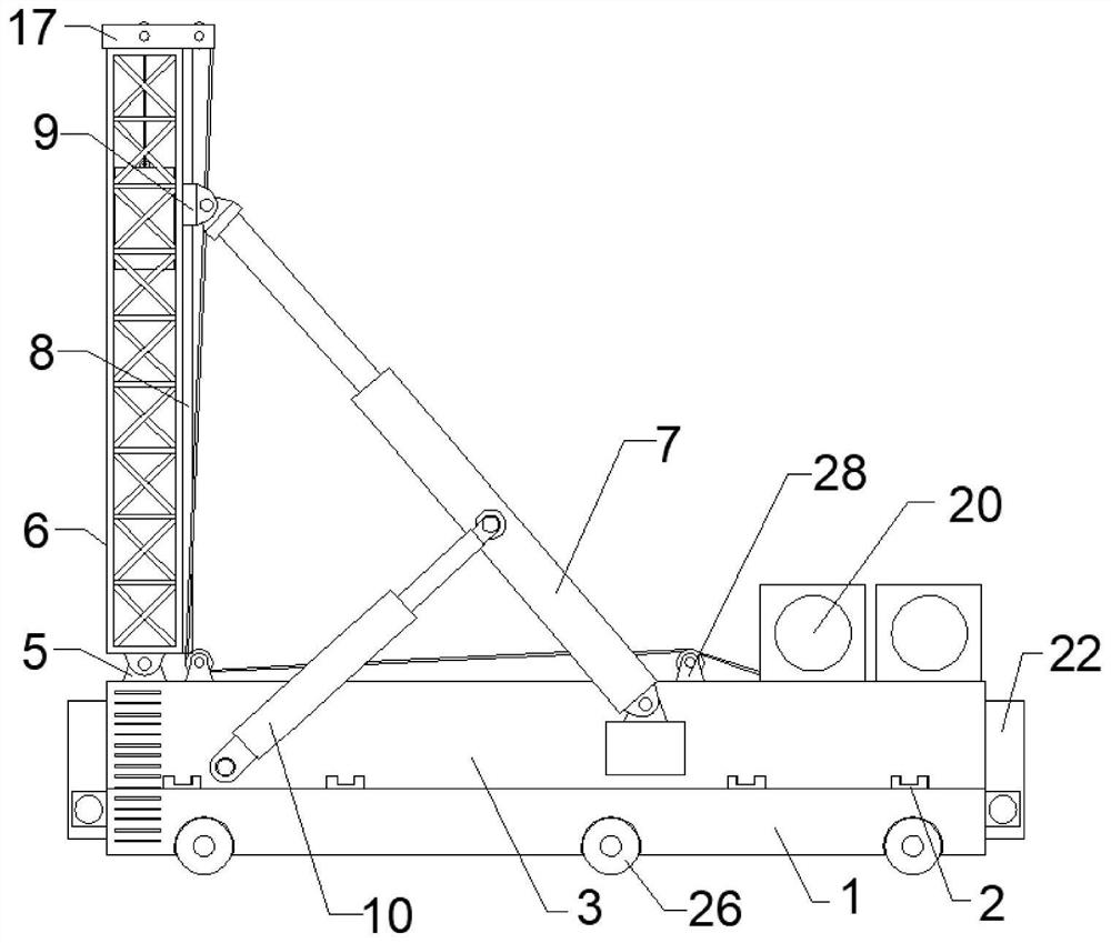
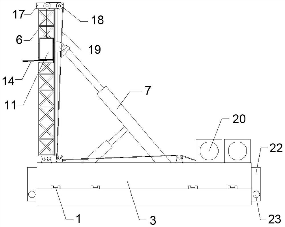
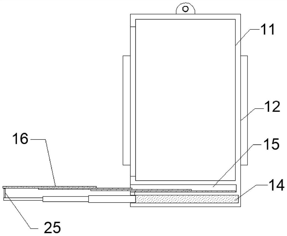
[0026] Such as Figure 1-6 As shown, a high-safety electric emergency repair tower lifting device includes a base 1, a moving base 3, a lifting tower 6, a threaded rod 21, a multi-stage hydraulic rod 14 and a slide plate 16, and guide rails are welded on the top of the base 1 2. The top of the guide rail 2 is slidably connected with a moving seat 3, and one end of the top of the moving seat 3 is rotated through a bearing seat 5 to install a lifting tower 6, and a car 11 is arranged inside the lifting tower 6, and the inside of the car 11 A plate groove 15 is opened at the bottom, and slide plates 16 are stacked and arranged in the plate groove 15. A multi-stage hydraulic rod 14 is fixedly installed in the car 11 and at the bottom of the plate groove 15, and the multi-stage hydraulic rod 14 outputs The end top is welded and connected with the end of the slide plate 16 at the top of the plate groove 15 through the support column 25, and the first slide rail 8 is welded on one si...

Embodiment 2

[0040] Such as Figure 1-6 As shown, a high-safety electric emergency repair tower lifting device includes a base 1, a moving base 3, a lifting tower 6, a threaded rod 21, a multi-stage hydraulic rod 14 and a slide plate 16, and guide rails are welded on the top of the base 1 2. The top of the guide rail 2 is slidably connected with a moving seat 3, and one end of the top of the moving seat 3 is rotated through a bearing seat 5 to install a lifting tower 6, and a car 11 is arranged inside the lifting tower 6, and the inside of the car 11 A plate groove 15 is opened at the bottom, and slide plates 16 are stacked and arranged in the plate groove 15. A multi-stage hydraulic rod 14 is fixedly installed in the car 11 and at the bottom of the plate groove 15, and the multi-stage hydraulic rod 14 outputs The end top is welded and connected with the end of the slide plate 16 at the top of the plate groove 15 through the support column 25, and the first slide rail 8 is welded on one si...


PUM


Abstract

The invention discloses a high-safety power line repair tower lifting device which comprises a base, a moving seat, a lifting tower, a threaded rod, a multi-stage hydraulic rod and sliding plates. Guide rails are distributed and welded to the top of the base; the moving seat is slidably connected to the tops of the guide rails; the lifting tower is rotatably mounted at one end of the top of the moving seat through a bearing seat; a lift car is arranged in the lifting tower; a plate groove is formed in the bottom in the lift car; the sliding plates are arranged in the plate groove in a stacked mode; and the multi-stage hydraulic rod is fixedly installed in the lift car and located at the bottom of the plate groove. The whole power line repair tower lifting device is flexible and convenient to use so as to be be conveniently transferred and moved to various regional thermal electric power line repair places by personnel, is provided with a good lifting and transverse displacement adjusting mechanism so as to facilitate the personnel to better repair an electric power mechanism, and can be well folded and stored after being used so as to be capable of greatly reducing the difficulty in transportation by the personnel.

Description

technical field [0001] The invention belongs to the technical field of electric power construction, and in particular relates to a high-safety electric emergency repair tower lifting device. Background technique [0002] With the development of society, the power and communication industries are becoming more and more important to people's lives, and they are inseparable from them at all times. Therefore, once the line fails, it will have a serious impact on people's lives. In order to ensure emergency repair work, each grassroots level is equipped with emergency repair vehicles, but the current electric emergency repair device has poor flexibility in use, which is not conducive to good adjustment by personnel, which makes the electric emergency repair work more limited. Contents of the invention [0003] The purpose of the present invention is to provide a high-safety electrical emergency repair tower lifting device, which is flexible and convenient to use, and can help p...

Claims


Application Information

Patent Timeline
IPC IPC(8): B66F7/20B66F7/28
CPCB66F7/20B66F7/28
Inventor 张清玲
Owner 张清玲
Why Eureka
Try Eureka