Air supply device

An air supply and airflow technology, applied in the field of air supply devices, can solve the problems of high temperature of the equipment, uncontrollable heat, and inability to screen out dust.

Inactive Publication Date: 2021-05-07
赵红红
View PDF0 Cites 0 Cited by
  • Summary
  • Abstract
  • Description
  • Claims
  • Application Information

AI Technical Summary

Problems solved by technology

[0005] In order to solve the above problems, the present invention provides an air supply device, which effectively avoids the defects in the current technology that the heating air flow cannot

Method used


Image

  • Air supply device
  • Air supply device
  • Air supply device

Examples


Embodiment Construction

[0019] The present invention will be further described below in conjunction with the accompanying drawings and embodiments.

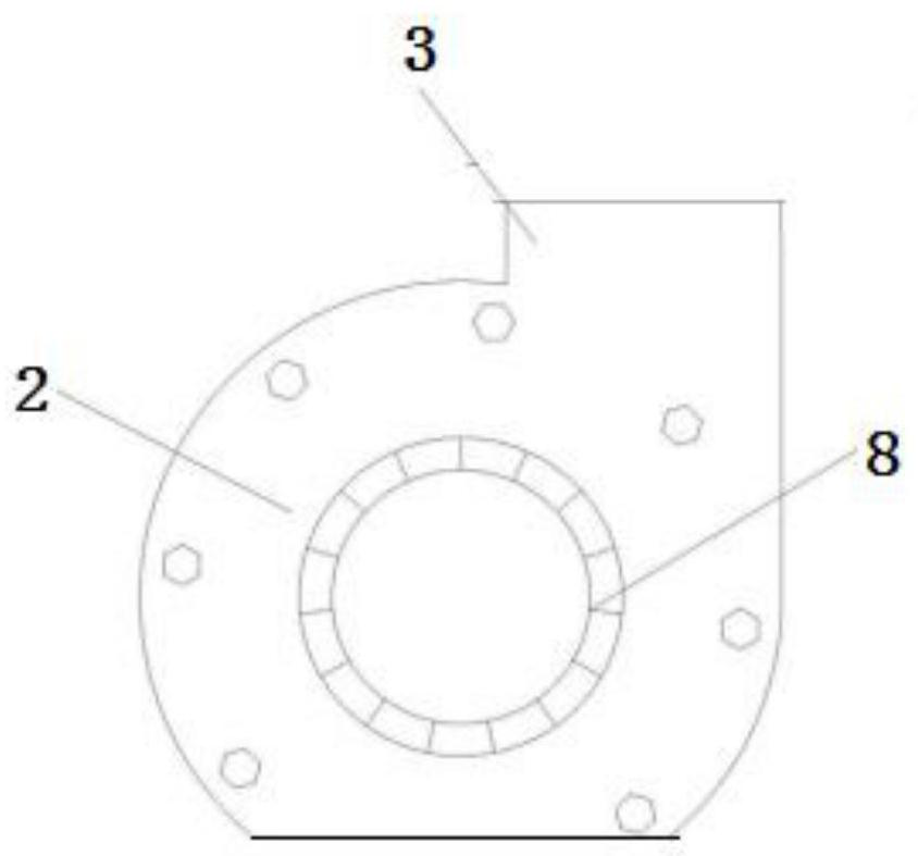
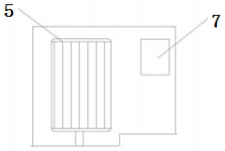
[0020] Such as Figure 1-Figure 3 As shown, the air delivery device includes an outer cover, and the air delivery hole 2 and the exhaust hole 3 are opened on the outer cover, as well as the motor 5 installed near the air delivery device and the paddle 8 installed in the outer cover, and the air delivery hole 2 is paired. The air flow has the function of guiding. The roller of the paddle 8 is connected to the motor 5 shaft, and when the motor 5 rotates, it will pull the paddle 8 to rotate together. A reverse airflow occurs inside, and the airflow outside the outer cover reaches the outer cover through the air supply hole, so as to realize the air flow.

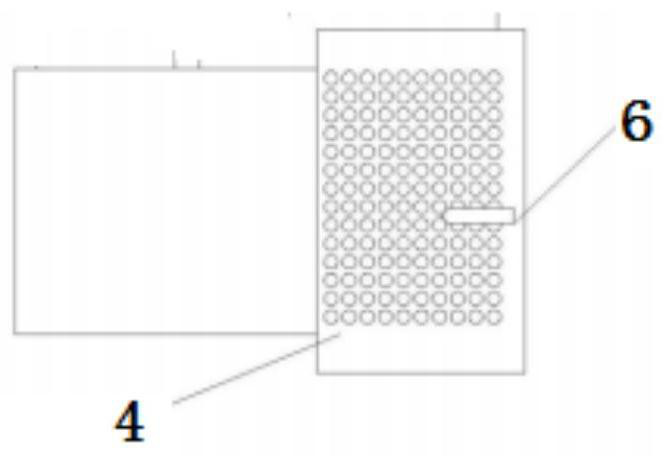
[0021] The exhaust hole 3 of the air supply device is equipped with a screen 4 for screening dust, and the screen 4 is a mesh plate with a two-stage structure, and the air flow through the screen 4 is i...


PUM


Abstract

An air supply device comprises an outer cover, and an air supply hole and an exhaust hole are formed in the outer cover. A motor installed near the air supply device and blades installed in the outer cover are further included, the air supply hole has the performance of guiding airflow, a roller of the blades is connected with a motor shaft, and the blades can be dragged to rotate together when the motor operates and rotates; and the blades discharge airflow in the outer cover out of the exhaust hole, reverse airflow appears in the outer cover, and the airflow outside the outer cover reaches the outer cover through the air supply hole. A screen for screening dust is installed on the exhaust hole of the air supply device, the screen is a net-shaped plate with a two-stage structure, and a temperature rising mechanism for rising the temperature of airflow passing through the screen is installed in the screen. Therefore, the defects that the temperature rise of equipment is too high, the service life of the air supply device is shortened and dust cannot be screened out since heat cannot be controlled because temperature rise airflow cannot be controlled are effectively overcome.

Description

technical field [0001] The invention relates to the technical field of air supply, in particular to an air supply device. Background technique [0002] The air supply device is a mechanism that improves the airflow pressure and feeds the airflow by virtue of the power generated during operation. It is an auxiliary airflow mechanism; the air supply device is generally applicable to workshops, basements, underground passages, coolers, transport aircraft, submarines and high-rise buildings. Air supply, ash removal and cooling, air supply and diversion of evaporators and charcoal burning chambers; cooling and air supply in airflow conversion equipment and air conditioners; dehumidification and classification of flour, air supply and drive of tunnel air sources and air boats. [0003] Under the influence of some manufacturing and preparation aspects, it will be necessary to raise the temperature of the air flow. The air supply device commonly used in the prior art can heat the ai...

Claims


Application Information

Patent Timeline
IPC IPC(8): F04D25/08F04D29/70F04D29/58F04D29/42
CPCF04D25/08F04D29/4206F04D29/582F04D29/701
Inventor 赵红红
Owner 赵红红
Why Eureka
Try Eureka