
Liquid crystal display panel and liquid crystal display device

A liquid crystal display panel and liquid crystal layer technology, applied in the direction of instruments, nonlinear optics, optics, etc., can solve the problems of increasing light loss rate, blue light damage to human eyes, and reducing light utilization rate, so as to reduce light loss rate and protect Eye health, improve the effect of light utilization

Inactive Publication Date: 2021-05-07
JRD COMM (SHENZHEN) LTD
View PDF11 Cites 0 Cited by
  • Summary
  • Abstract
  • Description
  • Claims
  • Application Information

AI Technical Summary

Problems solved by technology

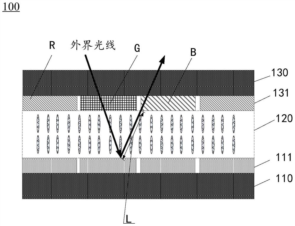
[0003] With the requirements of eye protection, the blue light carried by the light source is harmful to human eyes. To solve this problem, display manufacturers have introduced a liquid crystal display that does not need a backlight or a self-luminous light source to light up, such as a reflective liquid crystal display (Reflective Liquid Crystal Display, RLCD), the principle of light emission is that a layer of reflective layer is coated on the array substrate, and the color film substrate absorbs the external natural light. The natural light is transmitted through the color filter and then diverted through the liquid crystal layer, and then reaches the reflection layer of the array substrate and then passes through the color filter for the second time. After layering, the light will form an image in the human eye, which will greatly increase the loss rate of light, thereby reducing the utilization rate of light.

Method used


Image

  • Liquid crystal display panel and liquid crystal display device
  • Liquid crystal display panel and liquid crystal display device
  • Liquid crystal display panel and liquid crystal display device

Examples


Embodiment Construction

[0022] The following will clearly and completely describe the technical solutions in the embodiments of the application with reference to the drawings in the embodiments of the application. Apparently, the described embodiments are only some of the embodiments of the application, not all of them. Based on the embodiments in this application, all other embodiments obtained by those skilled in the art without making creative efforts belong to the scope of protection of this application.

[0023] It should be easily understood that the directional terms mentioned in the present invention, such as [upper], [lower], [front], [back], [left], [right], [inner], [outer], etc., only is the direction with reference to the attached drawings. Therefore, the directional terms used are used to illustrate and understand the present invention, but not to limit the present invention. In the figures, structurally similar elements are denoted by the same reference numerals. The terms "first" an...


PUM


Abstract

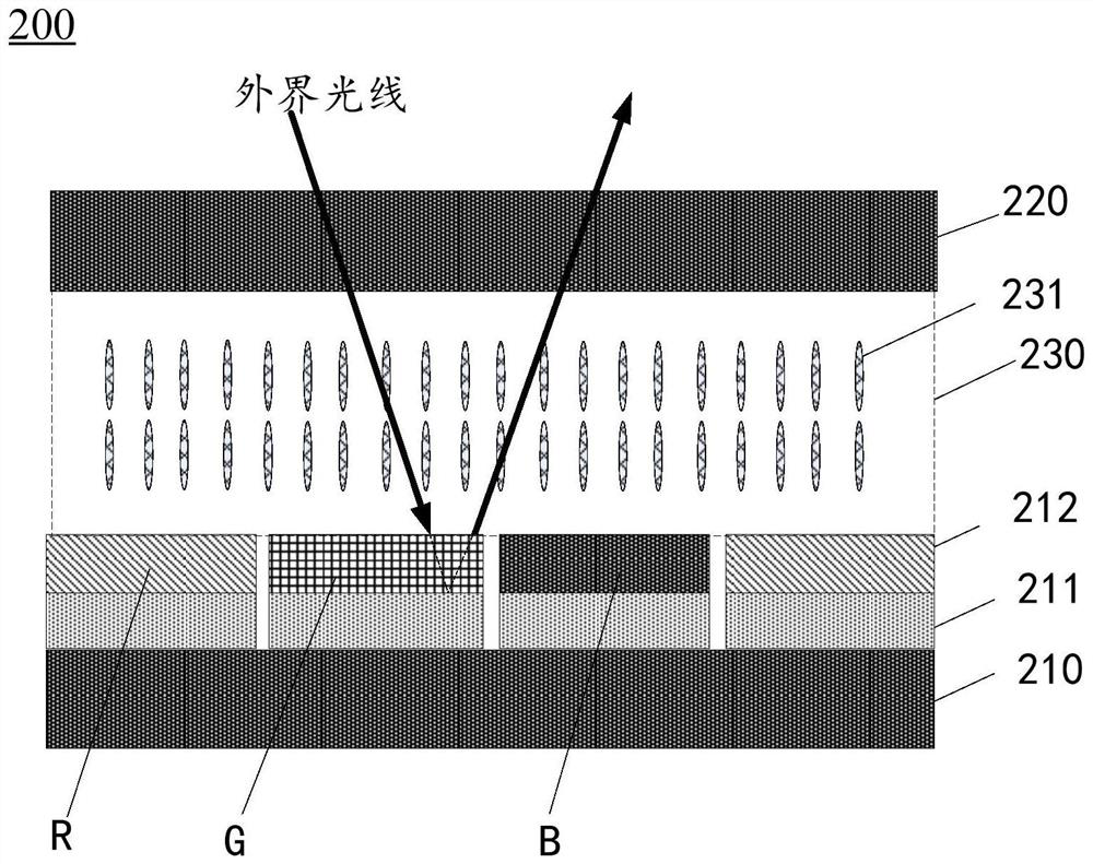
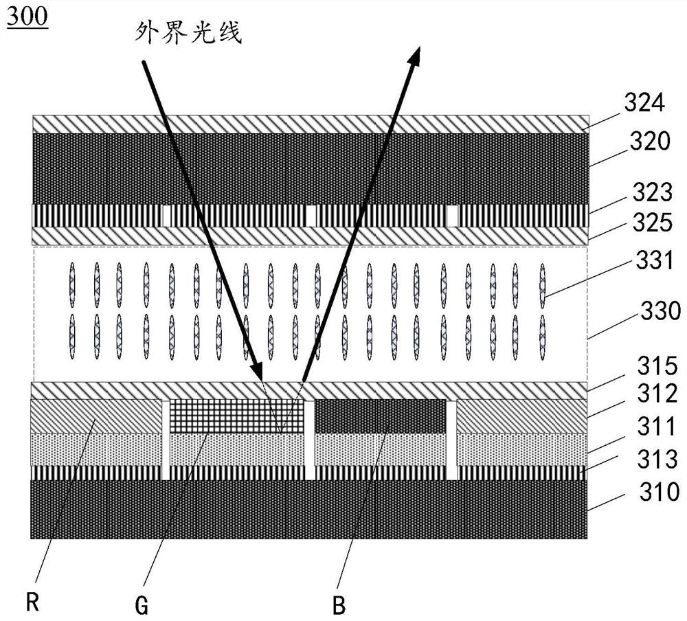
The invention relates to a liquid crystal display panel and a liquid crystal display device.The liquid crystal display panel comprises a first substrate, a second substrate and a liquid crystal layer located between the first substrate and the second substrate, a reflecting layer is arranged on the side, facing the liquid crystal layer, of the first substrate, and a color filter layer covering the reflecting layer is further arranged on the first substrate; when light rays enter the color filter layer through the second substrate, the reflecting layer reflects the light rays filtered by the color filter layer to the second substrate. According to the liquid crystal display panel and the liquid crystal display device, on the basis that light-source-free lighting is achieved, the light loss rate can be reduced, the light utilization rate can be increased, and the reflectivity of the liquid crystal display panel can be increased.

Description

technical field [0001] The present application relates to the field of panel technology, in particular to a liquid crystal display panel and a liquid crystal display device. Background technique [0002] Mobile phones and tablet computers are commonly used electronic devices in daily life, and electronic devices are usually equipped with LCD screens. Most of the existing LCD screens include an array substrate, a liquid crystal layer, and a color film substrate. The array substrate includes a backlight module, a light source, and a color film. The substrate includes a color filter. The light emitted by the light source enters the liquid crystal layer through the backlight module, and enters the color filter after being redirected by the liquid crystal molecules in the liquid crystal layer, and then passes through the color filter to present red, green, and blue colors. The different ratios of the three primary colors present different color requirements of the image. [0003...

Claims


Application Information

Patent Timeline
Patent Type & Authority Applications(China)
IPC IPC(8): G02F1/1335G02F1/1343
CPCG02F1/133514G02F1/134309G02F1/133553G02F1/136222G02F2203/02G02F1/133616G02F1/133618G02F1/133302G02F1/133528G02F1/13439G02F1/137
Inventor 林科于洋马记涛邱珠伟
Owner JRD COMM (SHENZHEN) LTD
Learn More