
Determination method of stress intensity factor for anisotropic materials with multiple round holes and multiple cracks

A stress intensity factor and anisotropic technology, applied in special data processing applications, instruments, complex mathematical operations, etc., can solve problems such as dependence, complexity, and difficulty in obtaining high-precision solutions

Active Publication Date: 2022-05-17
CENT SOUTH UNIV
View PDF2 Cites 0 Cited by
  • Summary
  • Abstract
  • Description
  • Claims
  • Application Information

AI Technical Summary

Problems solved by technology

However, there are few studies on the problem of anisotropic multi-circular holes-multiple cracks
For example, Fotuhi and Fariborz used the supersingular integral equation method to calculate the multi-hole-multi-crack interaction stress intensity factor of orthotropic materials under far-field stress. However, this method needs to solve complex supersingular integral equations; Hwu et al. The relationship between the boundary element surface stress and the finite element nodal force, a boundary-finite element coupling method is proposed to calculate the anisotropic multi-hole-multi-crack problem, this method is not suitable for the case of round holes and surfaces subject to surface stress ; Dwyer et al. proposed a boundary function method to calculate the anisotropic multi-hole-multi-crack problem under far-field stress. Approximation
It can be seen that the above method is limited to the calculation of isotropic or anisotropic multi-hole-multi-crack interaction stress intensity factors under far-field stress, without considering the surface stress of round holes and cracks, let alone the arbitrary distribution of surface stress
Moreover, these methods for studying anisotropic hole-crack problems need to solve complex singular integral equations, or it is difficult to obtain high-precision solutions

Method used


Image

  • Determination method of stress intensity factor for anisotropic materials with multiple round holes and multiple cracks
  • Determination method of stress intensity factor for anisotropic materials with multiple round holes and multiple cracks
  • Determination method of stress intensity factor for anisotropic materials with multiple round holes and multiple cracks

Examples


Embodiment 1

[0053] Preferred embodiment 1, the specific steps of the method for measuring the stress intensity factor of the multi-hole multi-crack anisotropic material disclosed in this embodiment are as follows.

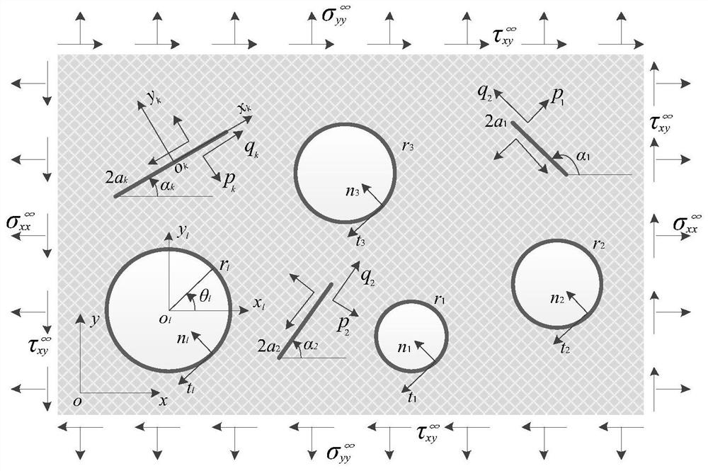
[0054] The first step is to construct an anisotropic body, such as figure 1 As shown, the anisotropic body contains L circular holes (radius r l ,l=1,2,3,…,L) and K cracks (half-length a k , inclination α k ,k=1,2,3,…,K), the far-field effect has uniform stress ( and ), the hole and the surface of the crack act on the surface of arbitrarily distributed normal stress and shear stress (n k , t k and p l ,q l ).

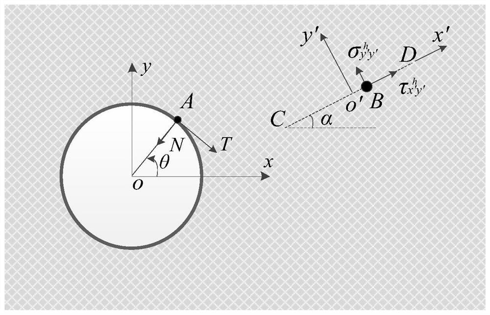
[0055] The second step is to construct a planar unit model with a single circular hole, such as figure 2 As shown, when the plane unit model contains a single circular hole (aperture r) and any point A(r, θ) of the anisotropic body acts on the concentrated force (N, T), any point B on the virtual crack CD (inclination angle α) normal and tangential stress ...

Embodiment 2

[0105] Preferred Embodiment 2. This embodiment is used to calculate isotropic materials. Such as Figure 4 As shown, construct an infinite isotropic flat plate (Poisson's ratio ν=0.3) containing a horizontal crack with a radius r and a length 2a (a=0.5r), and a uniform Brass stress σ acts on the vertical crack surface at infinity, s and t denote the horizontal and vertical distances between the center of the circle and the midpoint of the crack, respectively.

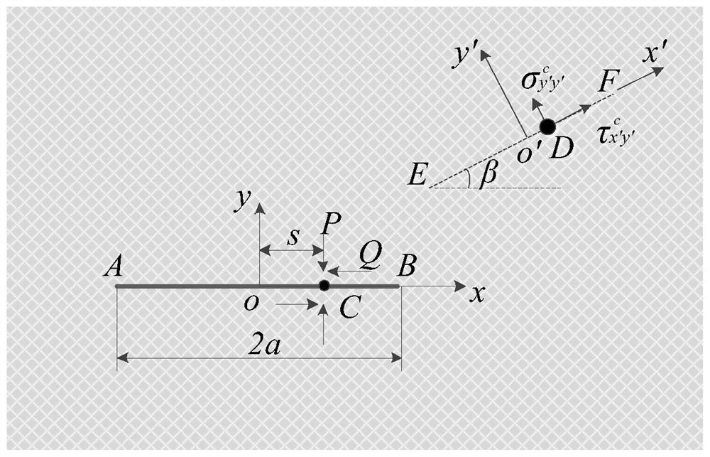
[0106] Let the two roots u of the characteristic equation of the anisotropic material j (j = 1, 2) are approximately equal, and the basic stress solution of the isotropic body with a single circular hole subjected to the concentrated force on the orifice surface is obtained approximately, and the crack inclination angle α in the basic solution is set to 0, and the stress caused by the concentrated force on the surface of the circular hole is obtained The normal and tangential stresses on the horizontal crack surface. ...

Embodiment 3

[0136] Preferred Embodiment 3. This embodiment can be used to calculate anisotropic materials. Such as Figure 5 As shown, construct an infinite anisotropic flat plate with a radius r and a length 2a (a=0.5r) inclined crack (inclination angle α=30°), and biaxial tensile stress acts at infinity Uniformly distributed surface stress n(n=-cos 2 θMPa), s represents the distance between the center of the circle and the midpoint of the crack. Anisotropic material properties are:

[0137]

[0138] S1: Make the crack inclination angle α=30 ° in the basic solution, obtain the surface normal direction and tangential stress of the inclined crack surface caused by the concentrated force on the surface of the circular hole;

[0139] S2: Determine the normal and tangential stresses on the surface of the circular hole caused by the concentrated force on the surface of the crack;

[0140] S3: Based on the derived basic solution and the stress boundary conditions of the circular hole an...


PUM


Abstract

The invention discloses a method for measuring the stress intensity factor of an anisotropic material with many circular holes and multiple cracks. The steps are as follows: taking the material to be tested as a prototype, constructing a plane unit model containing multiple circular holes and multiple cracks, and defining boundary conditions ; Construct a plane element model containing a single circular hole, and solve the basic stress solution of the model subjected to the concentrated force on the surface of the orifice according to the complex variable function Cauchy integral theory; construct a plane element model containing a single crack, according to the complex variable function Cauchy integral theory Solve the basic stress solution of the model subjected to the concentrated force on the surface of the crack; according to the obtained basic stress solution and stress boundary conditions, obtain the integral equation about the interaction surface stress of each circular hole and each crack; discretize the obtained integral equation It is a linear algebraic equation; the formula for calculating the stress intensity factor of the plane element model containing a single crack is derived, and the stress intensity factor of the plane element model under the interaction of multiple circular holes and multiple cracks is calculated in combination with the solved crack surface interaction surface stress.

Description

technical field [0001] The invention belongs to the technical field of fracture mechanics, in particular to a method for measuring the stress intensity factor of anisotropic materials with many round holes and many cracks. Background technique [0002] In rock mass engineering such as slopes, water conservancy projects, tunnels, and mineral mining, natural rocks often show obvious anisotropy characteristics, and often contain defects such as cracks inside, and the existence of cracks causes cracks in the rock mass structure. The stress is more concentrated, which reduces the mechanical properties of the rock mass structure and greatly increases the engineering risk factor. Since arranging suitable round holes near the crack can effectively reduce the stress intensity factor of the crack tip, the drilling arrest method is a common and effective method to improve the engineering strength of rock mass. In addition, in the exploitation of shale gas, the hydraulic fracturing tec...

Claims


Application Information

Patent Timeline
Patent Type & Authority Patents(China)
IPC IPC(8): G06F30/20G06F17/11G06F17/15G06F17/16G06F111/10G06F119/14
CPCG06F30/20G06F17/11G06F17/15G06F17/16G06F2119/14G06F2111/10
Inventor 饶秋华易威孙栋良
Owner CENT SOUTH UNIV
Learn More