Stepped cutter and inner cooling hole position design method thereof

A design method and hole location technology, which is applied to drilling/drilling equipment, drilling tool accessories, manufacturing tools, etc., can solve the problems of waste products generated by internal cooling holes, difficult accurate control of water outlet positions, and increased production costs.

Active Publication Date: 2021-05-11
ZHUZHOU CEMENTED CARBIDE CUTTING TOOLS CO LTD
View PDF7 Cites 0 Cited by
  • Summary
  • Abstract
  • Description
  • Claims
  • Application Information

AI Technical Summary

Problems solved by technology

However, in the actual production and processing of stepped tools, it is difficult to accurately control the water outlet position of the internal cooling hole in the large-diameter spiral groove. Usually, only the "trial and error" method can be used for trial production, which not only reduces the processing efficiency, but also easily occurs. The internal cooling hole is

Method used


Image

  • Stepped cutter and inner cooling hole position design method thereof
  • Stepped cutter and inner cooling hole position design method thereof
  • Stepped cutter and inner cooling hole position design method thereof

Examples


Embodiment Construction

[0030]The invention will be further described in detail below with reference to the accompanying drawings and specific embodiments.

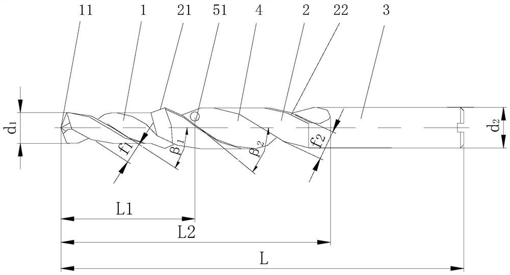
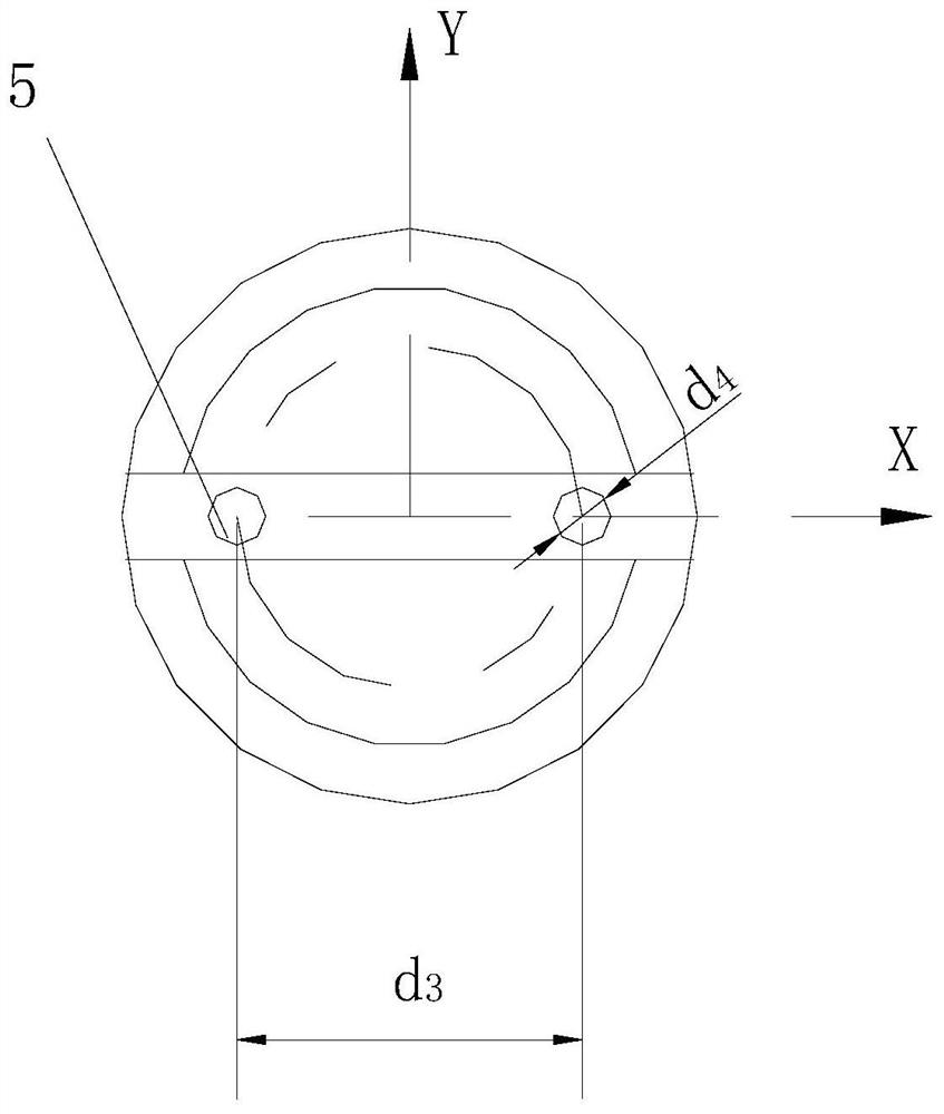
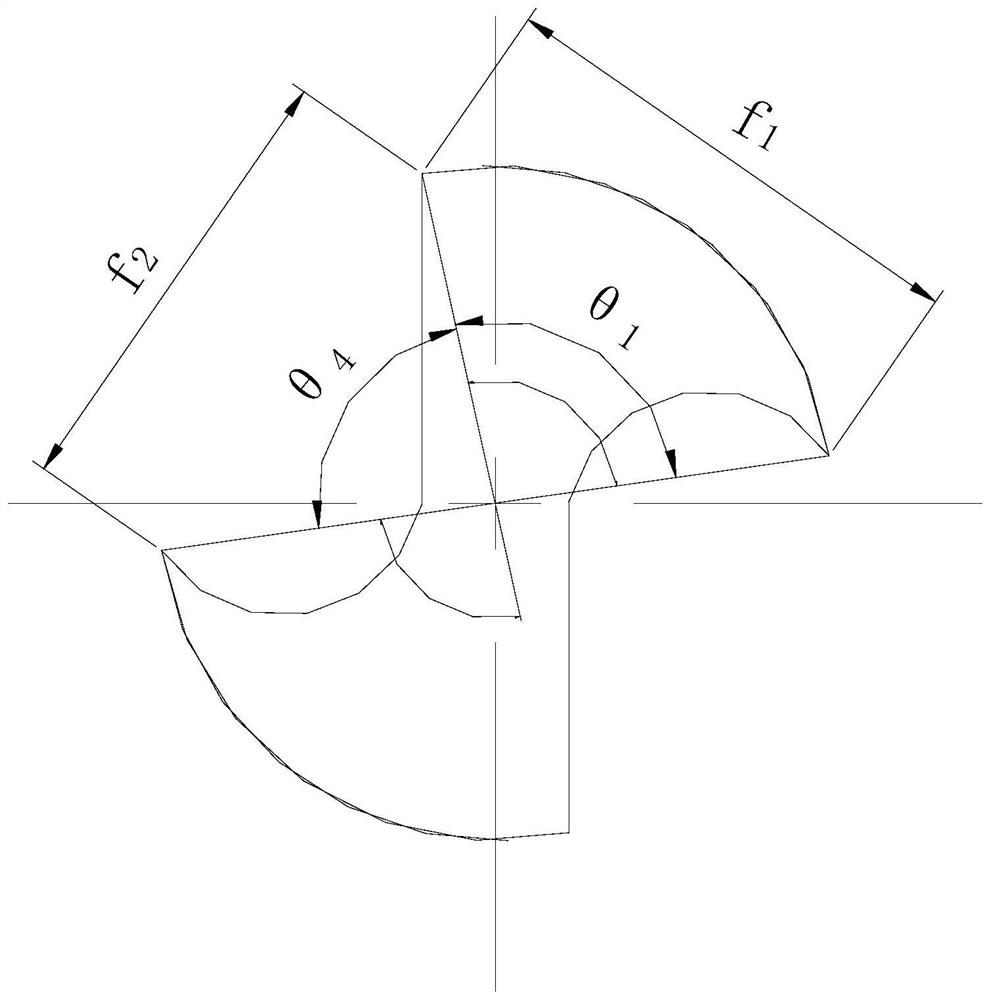
[0031]Figure 1 to 3One embodiment of the stepped tool of the present invention is shown in which the step cutting portion 2 and the handle portion 3 are sequentially provided, and the step cutting portion 2 is provided with a step cutting edge 21, at least one set. The spiral groove 4 and the spiral inner cold hole 5 corresponding to the spiral groove 4, the step cutting edge 21 is disposed at the transition of the small diameter cutting portion 1 and the step cutting portion 2, and the spiral groove 4 extends from the shank portion 2. By the small diameter cutting portion 1, the spiral inner cold hole 5 extends from the handle portion 3 to the step cutting portion 2 and the water port 51 is located in the spiral groove 4 and is adjacent to the step cutting edge 21, which does not affect the edge of the stepped tool The edge flap refers to the portion be...


PUM


Abstract

The invention discloses a stepped cutter and an inner cooling hole position design method thereof. The stepped cutter comprises a small-diameter cutting part, a stepped cutting part and a handle part which are sequentially arranged, the stepped cutting part is provided with a stepped cutting edge, at least one set of spiral grooves and spiral inner cooling holes corresponding to the spiral grooves, the stepped cutting edge is arranged at the transition position of the small-diameter cutting part and the stepped cutting part, the spiral groove extends to the rear cutter surface of the small-diameter cutting part from the connection position of the stepped cutting part and the handle part, the spiral inner cooling hole extends to the stepped cutting part from the handle part, and a water outlet is located in the spiral groove and is adjacent to the stepped cutting edge, cooling is sufficient, chip removal is smooth, and the quality of the machined surface is good; and the step cutter inner cooling hole position design method comprises the steps that the reasonable angle range of an auxiliary cutting edge spiral angle beta 2 meeting the design requirement is calculated, the auxiliary cutting edge spiral angle beta 2 is designated, and the method is accurate, efficient, stable and reliable.

Description

Technical field[0001]The present invention mainly relates to the field of metal cutting processing, and more particularly to a stepwise cutter and an inner cold hole position design method thereof.Background technique[0002]In the field of metal cutting processing, the stepper tool is a class of applications that have a wide range of tools, and common stepped tools include ladder drills, ladder hinges, composite step tools, and the like, and the stepwise tool can greatly improve processing efficiency.[0003]In the stepwise process, when the step cutting edge cuts into the workpiece, the cut force will suddenly occur. If the chips cannot be discharged smoothly, it is easy to make a broken blade, and therefore, in theoretical, the inner cold hole outlet is closer. The step cutting edge is conducive to the discharge of the chip, so that the cutting process can be carried out smoothly. However, ladder tools are difficult to accurately control in actual production and processing, and it is...

Claims


Application Information

Patent Timeline
IPC IPC(8): B23B51/06B23B51/08
CPCB23B51/08B23B51/06
Inventor 刘贺轩曾滔罗胜倪晓龙
Owner ZHUZHOU CEMENTED CARBIDE CUTTING TOOLS CO LTD
Why Eureka
Try Eureka