
Double-working-station stacking machine with temporary storage area and working method of butt joint area of double-working-station stacking machine

A buffer area and double-working technology, which is applied in the field of stackers, can solve the problems of no stacker, only one cache position, and low efficiency of picking up goods.

Pending Publication Date: 2021-05-11
SANLUX
View PDF0 Cites 3 Cited by
  • Summary
  • Abstract
  • Description
  • Claims
  • Application Information

AI Technical Summary

Problems solved by technology

[0003] The traditional stacker has the following defects: there is no cache position on the stacker or there is only one cache position per layer, and the efficiency of picking up the goods is low; the goods must be packaged in a fixed size or placed on a fixed-size carrier. There are certain requirements for the packaging method or loading. For some intelligent storage with a large number of products entering and leaving the warehouse, the normal daily cashier quantity can only be met by increasing the number of stackers.

Method used


Image

  • Double-working-station stacking machine with temporary storage area and working method of butt joint area of double-working-station stacking machine
  • Double-working-station stacking machine with temporary storage area and working method of butt joint area of double-working-station stacking machine
  • Double-working-station stacking machine with temporary storage area and working method of butt joint area of double-working-station stacking machine

Examples


Embodiment Construction

[0045] The present invention will be described in further detail below in conjunction with the embodiments, and the X and Y directions below are subject to the directions indicated in the drawings.

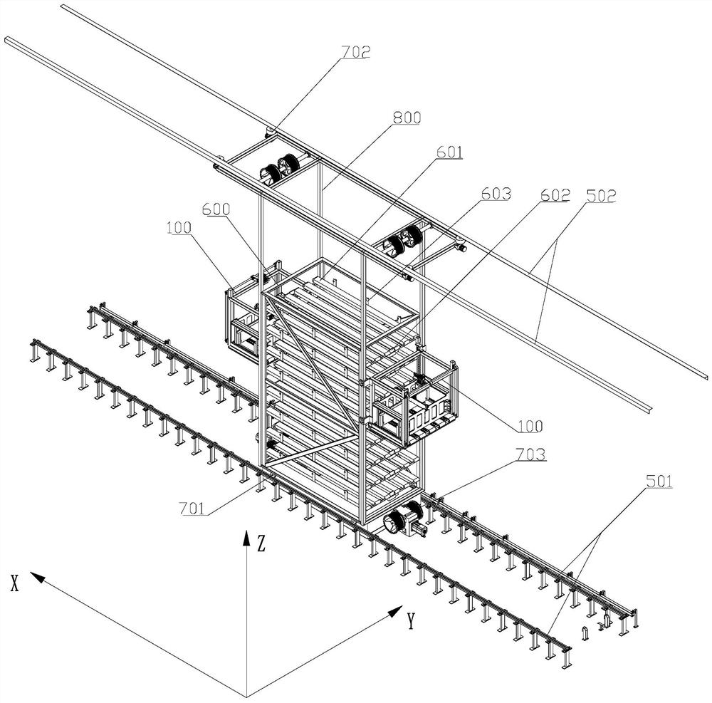
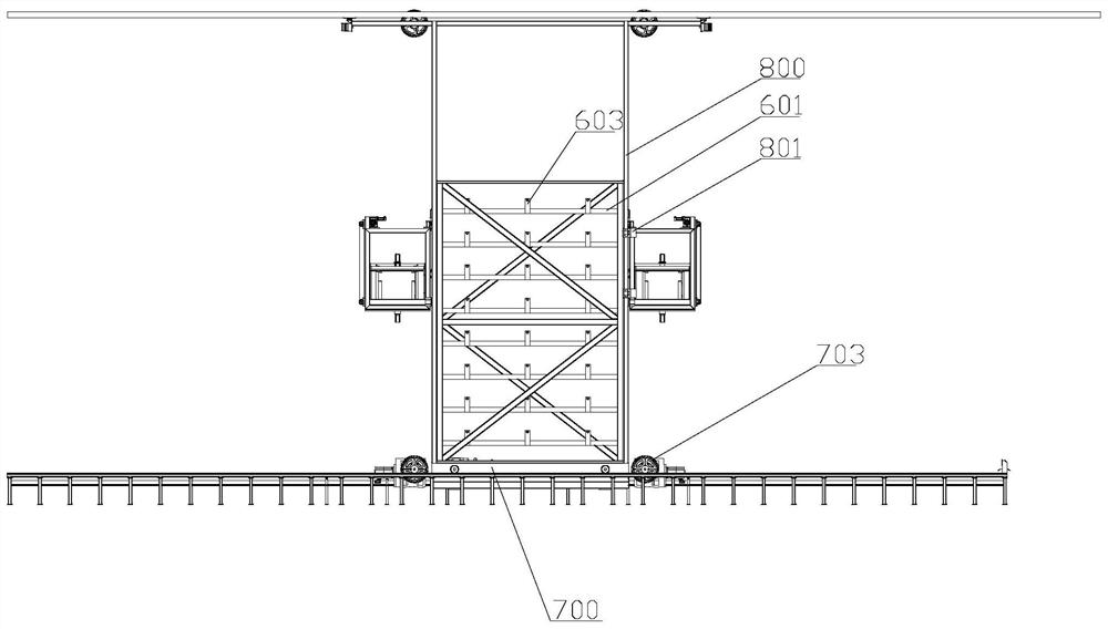
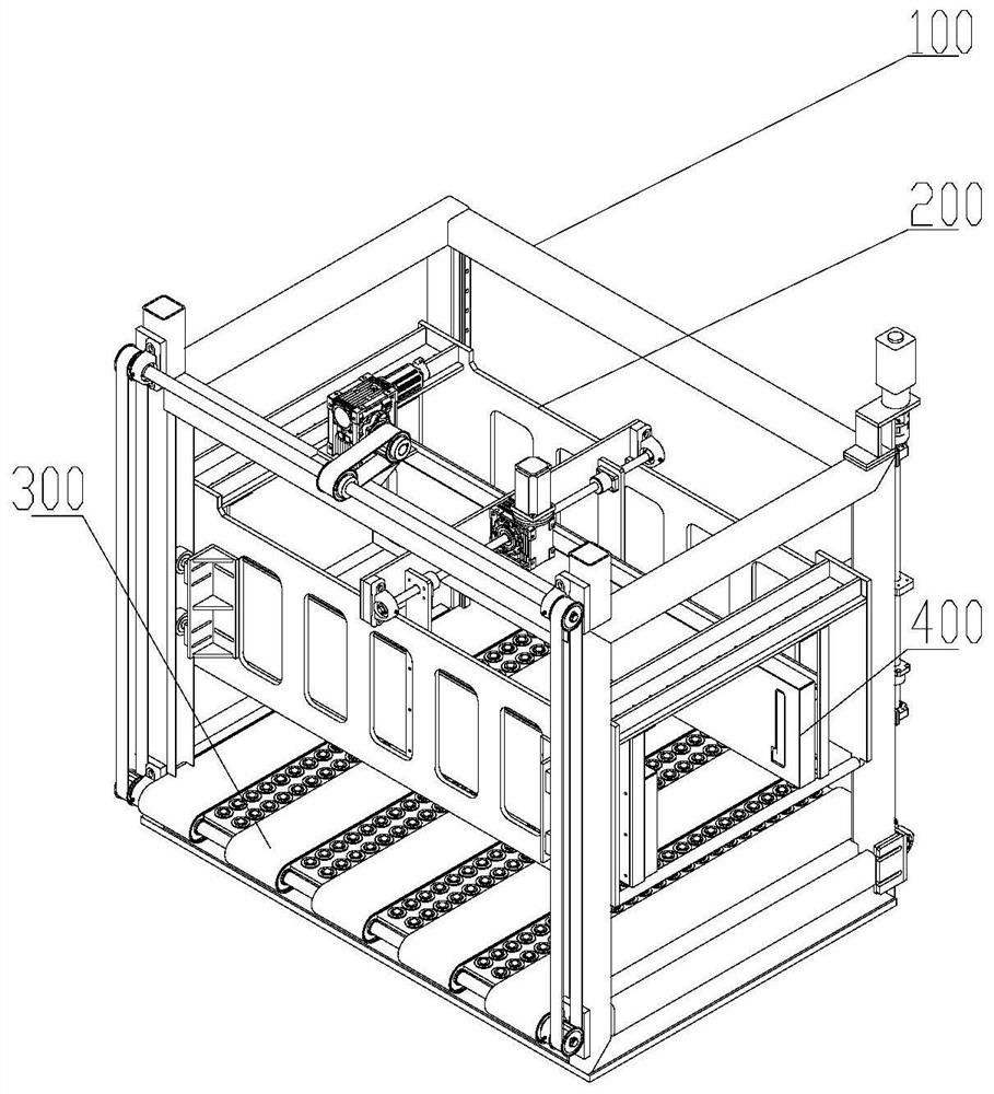
[0046] like figure 1 and 2 As shown, this embodiment proposes a dual-station stacker with its own buffer area, including a stacker seat 700 , a translation mechanism, a loading platform lifting mechanism 703 , a loading platform and a buffer area 600 . The stacker vehicle seat 700 is a plate structure, and the translation mechanism is installed on the stacker vehicle seat 700, including a bottom traveling wheel 701, a top traveling wheel 702 and a reduction motor driving the bottom traveling wheel 701 to operate. The buffer area 600 is fixed above the middle part of the stacker seat 700. Because the stacker has added a buffer area 600, it is heavier than the traditional stacker. It is necessary to set up and down a total of four tracks in the warehouse, namely figure 1 The doubl...


PUM


Abstract

The invention relates to a double-working-station stacking machine with a temporary storage area and a working method of a butt joint area of the double-working-station stacking machine. The double-working-station stacking machine comprises a stacking machine seat and a lifting mechanism, wherein the temporary storage area is arranged on the stacking machine seat, the temporary storage area comprises multiple layers of temporary storage conveying belts, the two ends, located in the conveying direction of the temporary storage conveying belt, of the temporary storage area are open, each layer of temporary storage conveying belt can be independently driven in a two-way mode, goods carrying tables are arranged at the two ends, located in the conveying direction of the temporary storage conveying belt, of the stacking machine seat, the lifting mechanism is used for driving the goods carrying tables to ascend and descend, the maximum ascending height of the goods carrying tables is not smaller than the sum of the height of the goods carrying tables and the height of the temporary storage area, a lower-layer conveying mechanism and a liftable upper-layer holding and clamping mechanism are arranged on the goods carrying tables, and the lower-layer conveying mechanism comprises a transportation conveying belt capable of being bidirectionally driven. The double-working-station stacking machine with the temporary storage area and the working method of the butt joint area of the double-working-station stacking machine have the advantages that the stacking machine is provided with a plurality of temporary storage positions, storage and taking integration can be achieved for a particularly long roadway, goods are stored and taken at the same time in the process of travelling from one end of the roadway to the other end of the roadway, the travelling time of the stacking machine is saved, and efficiency is improved.

Description

technical field [0001] The invention belongs to the technical field of stackers, and in particular relates to a double-working station stacker with its own buffer area and a working method for the docking area. Background technique [0002] Automated three-dimensional warehouse is a new concept in logistics warehousing. It is a warehouse that uses high-rise three-dimensional shelves to store materials, is controlled and managed by computers, and uses automatically controlled stackers to store and retrieve materials. Roadway stacker is a special crane developed along with the emergence of automated three-dimensional warehouse, usually referred to as stacker, is the most important lifting and transportation equipment in automated three-dimensional warehouse. The stacker runs along the track in the lane of the automated three-dimensional warehouse, and stores the materials at the entrance of the lane into the designated compartment, or takes out the materials in the designated ...

Claims


Application Information

Patent Timeline
IPC IPC(8): B65G1/04
CPCB65G1/0421B65G1/0428
Inventor 雷昌毅盛荣波殷彬富朱河龙
Owner SANLUX
Learn More