
Bailey truss cross beam clamp with handle rod

A Bailey frame and beam technology, applied in construction and other directions, can solve the problems of inconvenient disassembly and movement, affecting the movement and recyclability of the device, and poor versatility, so as to improve the stability, improve the safety of use, and improve the self-locking. sexual effect

Inactive Publication Date: 2021-05-11
江苏胜宏钢结构有限公司
View PDF0 Cites 1 Cited by
  • Summary
  • Abstract
  • Description
  • Claims
  • Application Information

AI Technical Summary

Problems solved by technology

[0002] Bailey sheets are also called Bailey frames, Bailey beams or trusses. During the construction of cast-in-place beams, the supports are often supported by Bailey sheets. The use of Bailey sheet supports has the advantages of fast speed, good composite structure system, and easy assembly. It can also play an effective role in terms of strength, stiffness, stability and overall performance. Therefore, it is currently in a period of rapid development of high-rise buildings. Higher and taller buildings are constantly emerging, and the application of top formwork systems is becoming more and more extensive. , when the Bailey frame is installed, it is usually connected by fixed welding of the Bailey frame and the beam. This installation method is stable and reliable, but these connection methods are not universal, and it is not easy to disassemble and move at any time, which seriously affects the later stage of the device. Mobility and recyclability, for which we propose a barley beam clamp with bar

Method used


Image

  • Bailey truss cross beam clamp with handle rod
  • Bailey truss cross beam clamp with handle rod
  • Bailey truss cross beam clamp with handle rod

Examples


Embodiment Construction

[0015] The following will clearly and completely describe the technical solutions in the embodiments of the present invention with reference to the accompanying drawings in the embodiments of the present invention. Obviously, the described embodiments are only some, not all, embodiments of the present invention. Based on the embodiments of the present invention, all other embodiments obtained by persons of ordinary skill in the art without making creative efforts belong to the protection scope of the present invention.

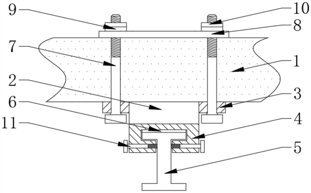
[0016] see figure 1 , figure 2 with image 3 , the present invention provides a technical solution: a barley frame crossbeam fixture with a bar, comprising a parallel barley frame reinforcement chord 1, the bottom of the bailey frame reinforcement chord 1 is equipped with a hoisting block 2, a hoisting block 2 Mounting lugs 3 are fixedly welded on the left and right side walls, the bottom of the hoisting block 2 is fixedly welded with a clamping seat 4, the...


PUM


Abstract

The invention discloses a bailey truss cross beam clamp with a handle rod in the technical field of bailey truss cross beam clamp with a handle rod; a hoisting block is assembled at the bottom of a bailey truss reinforcing chord member, mounting lugs are fixedly welded to the left side wall and the right side wall of the hoisting block, and a clamping seat is fixedly welded to the bottom of the hoisting block; a cross beam is assembled in the clamping base in an inserted mode, a protective pad matched with the cross beam is fixedly arranged in the clamping base in a nested mode, fastening bolts are assembled on the mounting lugs, and an anti-loosening base plate is assembled on the top of the bailey truss reinforcing chord member; The top end of each fastening bolt penetrates through the bailey truss reinforcing chord member and the anti-loosening base plate and then is fixedly connected with a fastening nut in a threaded mode, an anti-loosening nut connected to the outer wall of each fastening bolt in a threaded mode is arranged above the fastening nut, fastening screws matched with the cross beam are connected to the left side wall and the right side wall of the clamping base in a threaded mode, and the self-locking performance of the fastening nuts is improved; the installation stability of the structure is guaranteed, and the use safety of the device is improved.

Description

technical field [0001] The invention relates to the technical field of a beam clamp for a Bailey frame with a handle, in particular to a beam clamp for a Bailey frame with a handle. Background technique [0002] Bailey sheets are also called Bailey frames, Bailey beams or trusses. During the construction of cast-in-place beams, the supports are often supported by Bailey sheets. The use of Bailey sheet supports has the advantages of fast speed, good composite structure system, and easy assembly. It can also play an effective role in terms of strength, stiffness, stability and overall performance. Therefore, it is currently in a period of rapid development of high-rise buildings. Higher and taller buildings are constantly emerging, and the application of top formwork systems is becoming more and more extensive. , when the Bailey frame is installed, it is usually connected by fixed welding of the Bailey frame and the beam. This installation method is stable and reliable, but th...

Claims


Application Information

Patent Timeline
Patent Type & Authority Applications(China)
IPC IPC(8): E01D15/133
CPCE01D15/133
Inventor 谢宏逵
Owner 江苏胜宏钢结构有限公司
Learn More