
lens assembly

A component and lens technology, which is applied in the field of lens components, can solve the problems of limited application range and achieve the effects of improved positioning and control accuracy, good rigidity, and smooth movement

Active Publication Date: 2022-03-25
北京可利尔福科技有限公司
View PDF11 Cites 0 Cited by
  • Summary
  • Abstract
  • Description
  • Claims
  • Application Information

AI Technical Summary

Problems solved by technology

There are many ways to drive the lens, but due to reliability, structural rigidity and manufacturing cost, the application range is limited

Method used


Image

  • lens assembly
  • lens assembly
  • lens assembly

Examples


Embodiment Construction

[0037] The specific embodiments of the present disclosure will be described in detail below with reference to the accompanying drawings. It should be understood that the specific embodiments described herein are only used to illustrate and explain the present disclosure, but not to limit the present disclosure.

[0038] In the present disclosure, unless stated to the contrary, directional words such as "inner, outer" are used with respect to the contours of the corresponding parts. In addition, the terms "first, second" and the like used in the embodiments of the present disclosure are used to distinguish one element from another element, and have no order or importance. Where the following description refers to the drawings, the same numerals in different drawings refer to the same or similar elements unless otherwise indicated.

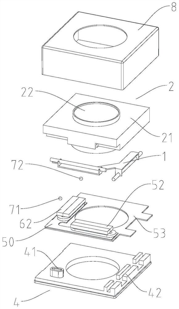
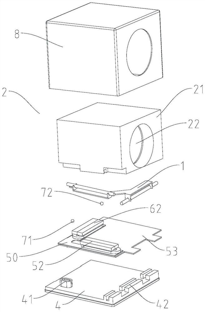
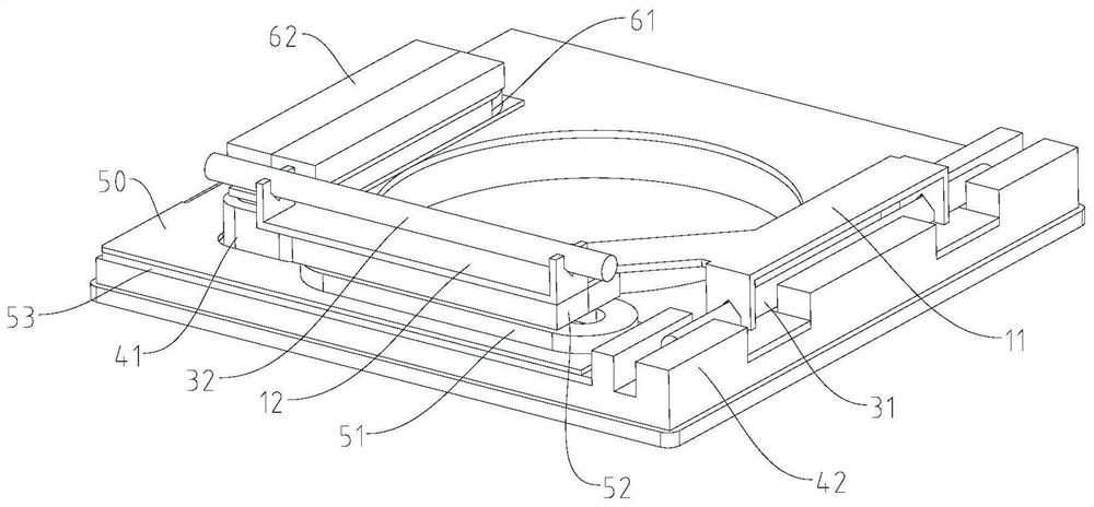
[0039] like figure 1 , figure 2 and Figure 12 As shown, the present disclosure provides a lens assembly comprising a lens module 2 and a lens...


PUM


Abstract

The present disclosure relates to a lens assembly, including a lens module and a lens driving mechanism for driving the lens module to move relative to an image sensor. The lens driving mechanism includes: a base, fixedly installed on the image sensor; a bearing structure, used for installing the lens module; The first slide rail, the carrying structure is slidably installed on the base through the first slide rail; the second slide rail, the extension direction of the second slide rail is different from the extension direction of the first slide rail, and the lens module can be moved through the second slide rail Slidingly installed on the carrying structure; the first electromagnetic generating device is used to generate electromagnetic induction to drive the carrying structure to move along the first slide rail; the second electromagnetic generating device is used to generate electromagnetic induction to drive the lens module along the second slide rail move. The lens module always moves linearly along the slide rail and is supported by the slide rail, which makes the movement of the lens module more stable and has high motion precision, ensures that the optical axis of the lens will not be deflected, and improves the definition of imaging.

Description

technical field [0001] The present disclosure relates to the technical field of lenses, and in particular, to a lens assembly. Background technique [0002] An optical system is a system for imaging or optical information processing, which can be applied in various fields, such as a camera lens of a mobile phone, a camera or a lens of projection technology. With the wider application of optical systems, users are more and more pursuing optical systems with high-definition imaging. During use of the lens, handheld devices or other external movements may cause the camera to shake. When the shutter speed is slow, the jitter reduces the sharpness of the image. At the same time, for the sensor chip that detects whether the image is in focus through the lens, the jitter will also slow down the focusing speed. Therefore, in order to minimize the negative impact of jitter on photography, a lens drive mechanism is introduced to counteract jitter. There are many ways to drive the ...

Claims


Application Information

Patent Timeline
Patent Type & Authority Patents(China)
IPC IPC(8): G03B5/00G03B30/00
CPCG03B5/00
Inventor 董怿
Owner 北京可利尔福科技有限公司
Learn More