Composite three-level double-buck inverter, and control method and system thereof

A control method and inverter technology, applied in the direction of electrical components, AC power input conversion to DC power output, output power conversion device, etc., can solve high reverse recovery loss, increase grid-connected current harmonic content, reduce Inverter power quality and other issues

Pending Publication Date: 2021-05-14
YIBIN VOCATIONAL & TECH COLLEGE
View PDF0 Cites 0 Cited by
  • Summary
  • Abstract
  • Description
  • Claims
  • Application Information

AI Technical Summary

Problems solved by technology

[0004] The purpose of the present invention is to provide a composite three-level double-buck inverter and its control method and system, to solve the problem that the composite three-level...

Method used


Image

  • Composite three-level double-buck inverter, and control method and system thereof
  • Composite three-level double-buck inverter, and control method and system thereof
  • Composite three-level double-buck inverter, and control method and system thereof

Examples


Embodiment 1

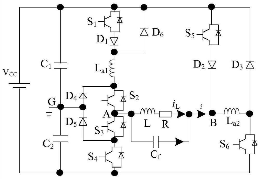
[0053] A compound three-level double-buck inverter, such as figure 2 As shown, the inverter is mainly composed of DC voltage source Vcc, supporting capacitor C 1 , support capacitance C 2 , power switch tube S 1 , power switch tube S 2 , power switch tube S 3 , power switch tube S 4 , power switch tube S 5 , power switch tube S 6 , power diode D 1 , power diode D 2 , power diode D 3 , power diode D 4 , power diode D 5 , power diode D 6 , filter inductance L a1 , filter inductance L a2 , filter inductor L and filter capacitor C f And the composition of the load resistance R;

[0054] where the support capacitor C 1 One end of the DC voltage source Vcc is connected to the positive pole of the support capacitor C 1 The other end of the support capacitor C 2 One end of the connection, support capacitor C 2 The other end of the DC voltage source Vcc is connected to the negative pole;

[0055] Power switch tube S 1 The collector of the DC voltage source Vcc is ...

Embodiment 2

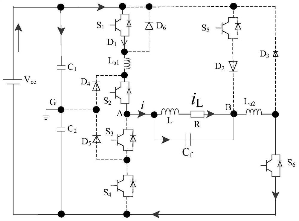
[0064] In this embodiment, the unipolar dual-carrier modulation method is used to control the working mode of the composite three-level double-buck inverter proposed in the above-mentioned embodiment 1. During specific implementation, the Figure 9 shown in the modulation method and Figure 10 The logic control diagram shown in the figure realizes the power switch tube S 1 , power switch tube S 2 , power switch tube S 3 , power switch tube S 4 , power switch tube S 5 and the power switch tube S 6 on or off. The existing SPWM control principle is to use a reference sine wave and a triangular carrier wave for handover to obtain a pulse signal, which is used to control the switching of the power switch tube. However, the five-level inverter of this application needs to modulate the signal u c After rectification, the triangular carrier V with two frequencies and amplitudes equal C1 and V C2 compared to obtain two pulse signals A 1 and B 1 . Simultaneously with modulat...


PUM


Abstract

The invention discloses a composite three-level double-buck inverter, and a control method and system thereof. The inverter comprises a DC voltage source Vcc, a support capacitor C1, a support capacitor C2, a power switch tube S1, a power switch tube S2, a power switch tube S3, a power switch tube S4, a power switch tube S5, a power switch tube S6, a power diode D1, a power diode D2, a power diode D3, a power diode D4, a power diode D5, a power diode D6, a filter inductor La1, a filter inductor La2, a filter inductor L, a filter capacitor Cf and a load resistor R. The invention aims to provide a composite three-level double-buck inverter, and a control method and system thereof, and solves problems that in the prior art, dead time needs to be set for a same-bridge-arm switching tube of a composite three-level bridge inverter, the harmonic content of a load current is increased, the electric energy quality of the inverter is reduced, a reverse recovery loss is high, and reliability is low.

Description

technical field [0001] The invention relates to the technical field of inverters, in particular to a composite three-level double-buck inverter and a control method and system thereof. Background technique [0002] The composite three-level bridge inverter in the prior art is as figure 1 As shown, it is composed of a three-level bridge arm and a two-level bridge arm. Compared with two bridge arms using three-level, its control is simple and easy to implement, and it is suitable for small and medium-sized Single-phase inverters for power applications. [0003] However, since the composite three-level bridge inverter is a bridge structure, the switching tubes of the same bridge arm have the problem of bridge arm direct connection, so it is necessary to set a dead time, and the introduction of the dead time will increase the grid-connected current resonance. The wave content reduces the power quality of the inverter. In addition, because the body diode of the switch tube of t...

Claims


Application Information

Patent Timeline
IPC IPC(8): H02M7/483H02M7/5387H02M1/38
CPCH02M1/38H02M7/483H02M7/5387
Inventor 代云中李泓廷鲁庆东罗钟雨游元庆刘勇屈珣刘健洋林虹宇梅清洪张鑫坤彭宇峰程健钊曹竞
Owner YIBIN VOCATIONAL & TECH COLLEGE
Why Eureka
Try Eureka