Metal material laser cutting device
A laser cutting, metal material technology, applied in laser welding equipment, metal processing equipment, welding equipment and other directions, can solve the problem of unable to remind and warn, laser cutting equipment does not have temperature detection function, etc.
- Summary
- Abstract
- Description
- Claims
- Application Information
AI Technical Summary
Problems solved by technology
Method used
Image
Examples
Embodiment 1
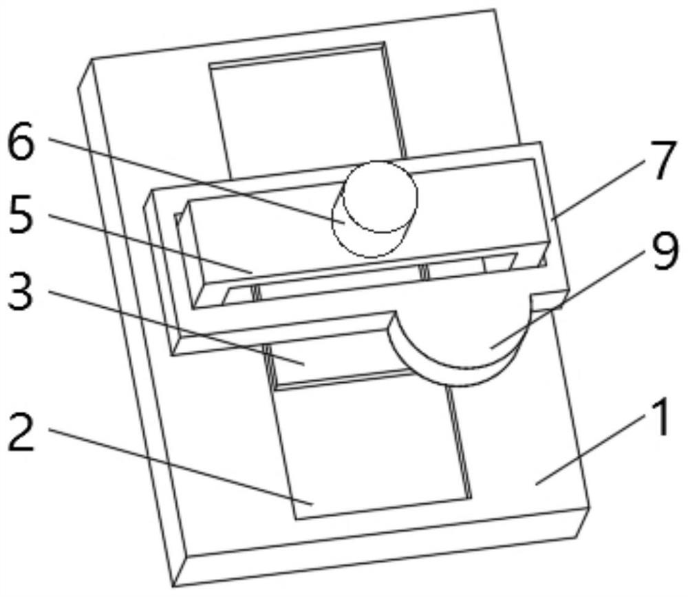
[0032] see Figure 1-4 , the present invention provides a technical solution: a metal material laser cutting device, including a cutting table 1, the top of the cutting table 1 is provided with a track groove 2, the inner bottom of the track groove 2 is slidably connected with a support plate 3, the cutting table 1 The top is located above the track groove 2 and a support frame 5 is installed. A laser 6 is installed on the top of the support frame 5. The laser 6 penetrates the support frame 5 and extends to the bottom of the support frame 5. The outside of the support frame 5 is provided with a detection frame 7. A detection device 8 is installed inside the detection frame 7 .
[0033] The detection device 8 includes a detection groove 801, one side of the detection groove 801 runs through the detection frame 7, a glass plate 802 is installed between the two sides of the inner wall of the detection groove 801, and a reinforcing column 803 is evenly installed between the two si...
Embodiment 2
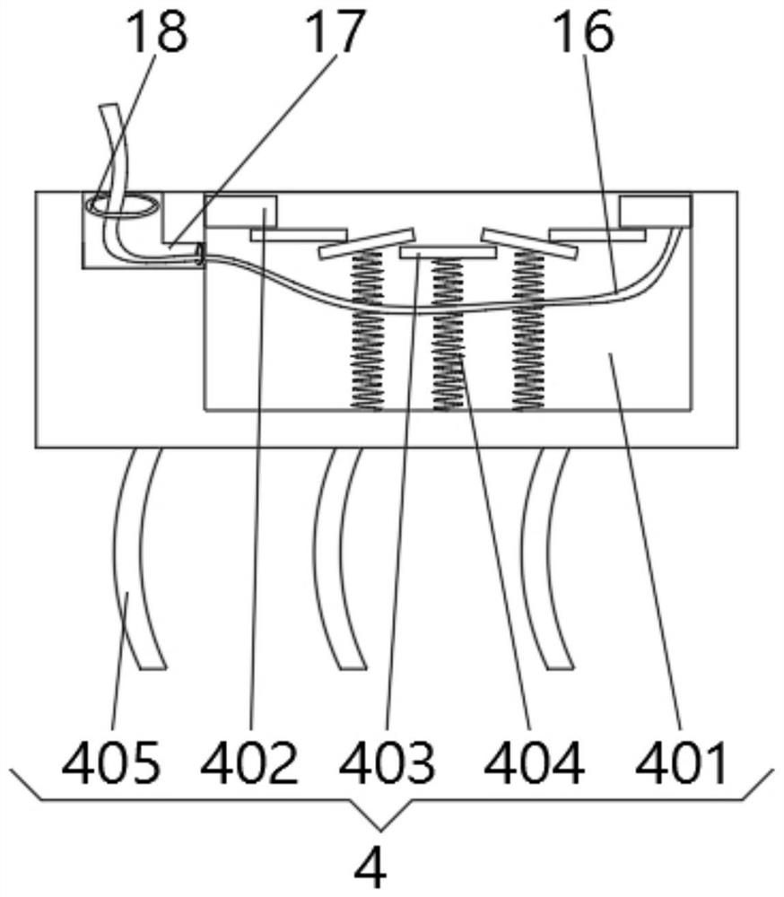
[0036] see Figure 1-4 , the present invention provides a technical solution: on the basis of Embodiment 1, a deformation device 4 is installed on the top of the support plate 3, the deformation device 4 includes a deformation groove 401, and both sides of the inner wall of the deformation groove 401 are fixedly connected with a fixed plate 402 The two sides of the fixed plate 402 are rotationally connected with a pressure plate 403, the bottom of the pressure plate 403 is fixedly connected with the inner bottom of the deformation groove 401 by a pressure spring 404, and the bottom of the support plate 3 is evenly equipped with an elastic plate 405.
[0037] When in use, the metal material to be cut is placed on the support plate 3, and the pressure-bearing plate 403 is squeezed downward by the metal material to press the pressure-bearing spring 404 for buffering, and the elastic plate 405 is not squeezed and bent at the same time for buffering, until The pressing plate 403 wrap...
Embodiment 3
[0039] see Figure 1-5 , the present invention provides a technical solution: on the basis of Embodiment 1, one side of the detection frame 7 is fixedly connected with an outer protrusion 9, and the top of the outer protrusion 9 is provided with a cooling tank 10, and the inside of the cooling tank 10 is installed with Refrigeration unit 11.
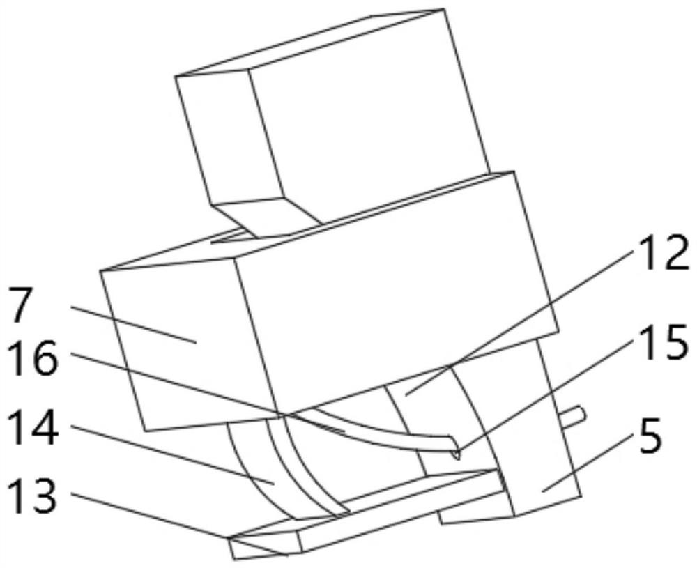
[0040] One side of the support frame 5 is provided with a receiving groove 12 , and one side of the receiving groove 12 is fixedly connected with a bottom plate 13 , and the top of the bottom plate 13 is fixedly connected with the detection frame 7 through a spring piece 14 .
[0041] One side of the support frame 5 is provided with a guide hole 15 , the bottom of the detection frame 7 is fixedly connected with a traction rope 16 , and the end of the traction rope 16 away from the detection frame 7 passes through the guide hole 15 and is connected with the support plate 3 .
[0042] The top of the support plate 3 is provided with a guid...
PUM
 Abstract
Description
Claims
Application Information
 - R&D
- Intellectual Property
- Life Sciences
- Materials
- Tech Scout
- Unparalleled Data Quality
- Higher Quality Content
- 60% Fewer Hallucinations
Browse by: Latest US Patents, China's latest patents, Technical Efficacy Thesaurus, Application Domain, Technology Topic, Popular Technical Reports.
© 2025 PatSnap. All rights reserved.Legal|Privacy policy|Modern Slavery Act Transparency Statement|Sitemap|About US| Contact US: help@patsnap.com


