Shampoo bottle body preparation system
A preparation system and water bottle technology, applied in the field of shampoo bottle preparation system, can solve the problem of shortening the molding time
- Summary
- Abstract
- Description
- Claims
- Application Information
AI Technical Summary
Problems solved by technology
Method used
Image
Examples
specific Embodiment approach 1
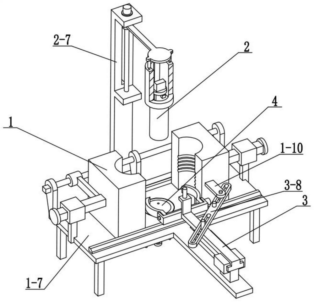
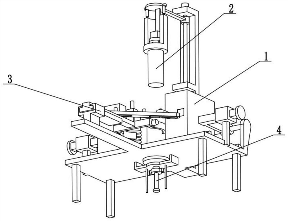
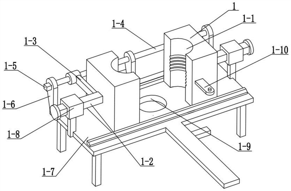
[0025] The present embodiment will be described below in conjunction with the drawings. The present invention relates to the technical field of bottle preparation, more specifically a shampoo bottle preparation system, including a forming liner 2, a suspension plate 2-4, and a cooling liquid cavity 2-9. , cooling liquid tank 2-10 and exchange water pump 2-11, described cooling liquid tank 2-10 is fixedly connected on the suspension board 2-4, and the molded liner 2 is fixedly connected at the bottom end of the suspension board 2-4, and the molding inner A cooling liquid inner cavity 2-9 is arranged inside the gallbladder 2, and the cooling liquid inner cavity 2-9 is connected and communicated with the cooling liquid tank 2-10 through the exchange water pump 2-11.
[0026] The exchange pump 2-11 delivers the coolant in the coolant tank 2-10 to the coolant cavity 2-9, and makes the coolant circulate continuously in the coolant tank 2-10 and the coolant cavity 2-9 flow, so that t...
specific Embodiment approach 2
[0028] The present embodiment will be described below in conjunction with the drawings. This embodiment will further illustrate Embodiment 1. The shampoo bottle preparation system also includes a crossbeam 2-3, a boom 2-5, a lifting screw 2-6, and a column 2- 7 and the lifting motor 2-8, the lifting motor 2-8 is fixedly connected to the top of the column 2-7, the lifting screw mandrel 2-6 is rotatably connected to the column 2-7, and the lifting screw mandrel 2-6 is fixedly connected to the lifting motor 2-7 8, the rear end of the crossbeam 2-3 is threadedly connected to the lifting screw 2-6, the top of the boom 2-5 is fixedly connected to the bottom end of the front end of the crossbeam 2-3, and the suspension plate 2-4 is fixedly connected to the suspension The bottom end of the arm 2-5 is slidably connected to the column 2-7 in cooperation with the rear end of the beam 2-3.
[0029] Use the lifting motor 2-8 to drive the lifting screw rod 2-6 to rotate, so that the lifting...
specific Embodiment approach 3
[0031] The present embodiment will be described below in conjunction with the drawings. This embodiment will further explain the second embodiment. The column 2-7 is provided with a chute, and the chute is used to slide on the column 2-7 in cooperation with the rear end of the beam 2-3. touch.
PUM
 Abstract
Description
Claims
Application Information
 - R&D
- Intellectual Property
- Life Sciences
- Materials
- Tech Scout
- Unparalleled Data Quality
- Higher Quality Content
- 60% Fewer Hallucinations
Browse by: Latest US Patents, China's latest patents, Technical Efficacy Thesaurus, Application Domain, Technology Topic, Popular Technical Reports.
© 2025 PatSnap. All rights reserved.Legal|Privacy policy|Modern Slavery Act Transparency Statement|Sitemap|About US| Contact US: help@patsnap.com


