Curtain wall system

A curtain wall and curtain wall panel technology, applied in the field of curtain wall systems, can solve problems such as difficulty in forming steel keels, affecting the visual effect of the overall curtain wall, and discontinuity of the bearing surface

Pending Publication Date: 2021-05-18
HUNAN GOLDWELL NEW MATERIALS TECH CO LTD +1
View PDF0 Cites 2 Cited by
  • Summary
  • Abstract
  • Description
  • Claims
  • Application Information

AI Technical Summary

Problems solved by technology

[0003] However, due to the difficulty in forming the steel keel, in order to ensure the sealing strength of the sealing strip between the glass plate and the steel keel, it is necessary to form a rubber groove on the bearing surface of the steel keel. The glue groove itself has a certain width. On the one hand, the glue The groove makes the bearing surface no longer continuous, r

Method used


Image

  • Curtain wall system
  • Curtain wall system
  • Curtain wall system

Examples


Embodiment 1

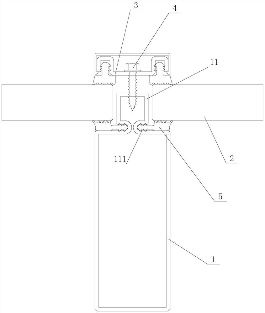
[0023] Such as figure 1 As shown, the first embodiment of the curtain wall system of the present invention includes a keel 1, a curtain wall panel 2, a pressure plate 3 and a locking bolt 4. The keel 1 is formed with a boss 11 extending out of the outline of the main body of the keel 1 on the bearing surface. , the curtain wall panel 2 is loaded on the bearing surface of the keel 1, the pressure plate 3 is pressed on the curtain wall panel 2, the locking bolt 4 is penetrated on the pressure plate 3 and is tightly connected with the boss 11, the curtain wall panel 2 and the keel 1 A sealing rubber strip 5 is provided, and a sinking groove 111 for preventing the sealing rubber strip 5 from falling off is formed on the boss 11 . During installation, the sealing rubber strip 5 is first clamped in the sinking groove 111, and the sealing rubber strip 5 covers the bearing surface of the keel 1, then the curtain wall panel 2 is loaded on the sealing rubber strip 5, and then the pressu...

Embodiment 2

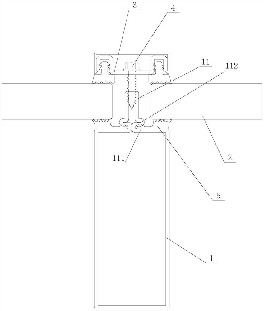
[0028] Such as figure 2 As shown, the second embodiment of the curtain wall system of the present invention, the curtain wall system is basically the same as Embodiment 1, the only difference is that in this embodiment, a lateral protrusion is formed on the boss 11 above the sinking groove 111 112. The arrangement of the lateral protrusions 112 strengthens the sinking groove 111 and the boss 11 at the same time, improving the connection strength.

Embodiment 3

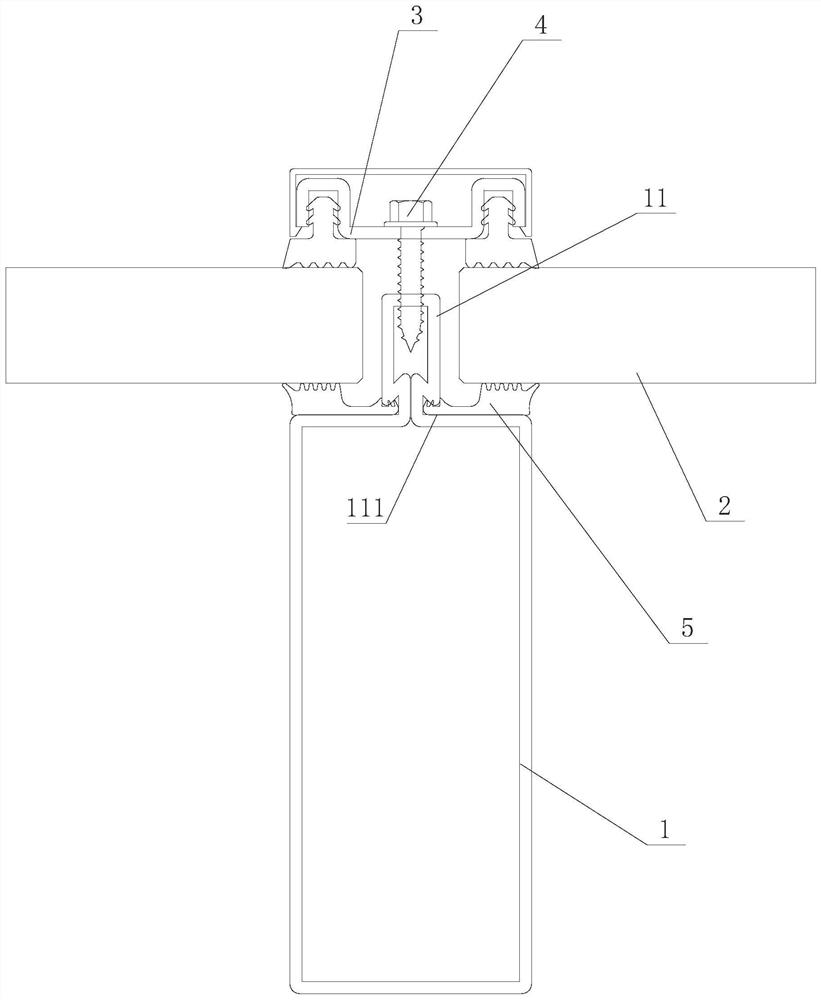
[0030] Such as image 3 As shown, the third embodiment of the curtain wall system of the present invention, the curtain wall system is basically the same as Embodiment 1, the only difference is that in this embodiment, the top surface of the sinking groove 111 is set as a slope, and the top slope makes the sinking groove 111 is an internal expansion groove as a whole. The setting of the inclined surface makes the sinking groove 111 an internal expansion groove as a whole, which further improves the effect of preventing the sealing rubber strip 5 from falling off.


PUM


Abstract

The invention discloses a curtain wall system. The curtain wall system comprises a keel, a curtain wall plate, a pressing plate and a locking bolt, wherein a boss extending out of the outline of a keel main body is formed on a bearing surface of the keel; the curtain wall plate is borne on the bearing surface of the keel; the pressing plate is pressed on the curtain wall plate; the locking bolt is arranged on the pressing plate in a penetrating manner and is fixedly connected with the boss; a sealing rubber strip is arranged between the curtain wall plate and the keel; and a rubber sinking groove for preventing the sealing rubber strip from dropping is formed in the boss. The curtain wall system has the advantages of stable and reliable structure, thin product and attractive appearance.

Description

technical field [0001] The invention mainly relates to the field of building doors and windows, in particular to a curtain wall system. Background technique [0002] Curtain walls generally include steel curtain walls and aluminum curtain walls. Aluminum curtain walls are easy to form, but they do not have fire resistance. The existing steel curtain wall includes steel keel, steel pressure plate, glass plate and bolts. The glass plate is connected to the steel keel through the steel pressure plate and bolts. A sealing strip will be placed between the glass plate, the steel keel and the steel pressure plate to ensure the sealing performance. and connection strength. [0003] However, due to the difficulty in forming the steel keel, in order to ensure the sealing strength of the sealing strip between the glass plate and the steel keel, it is necessary to form a rubber groove on the bearing surface of the steel keel. The glue groove itself has a certain width. On the one hand,...

Claims


Application Information

Patent Timeline
IPC IPC(8): E04B2/96E04B1/684
CPCE04B1/6812E04B2/96E04B2/967
Inventor 谢斌泉其他发明人请求不公开姓名
Owner HUNAN GOLDWELL NEW MATERIALS TECH CO LTD
Why Eureka
Try Eureka