
Equipment for efficiently removing accumulated ash on ash tank base of converter waste heat boiler

A waste heat boiler and converter technology, which is applied to lighting and heating equipment, removal of solid residues, and treatment of combustion products, etc., can solve the problems of incomplete and tight sealing, heavy soot, and high cost.

Pending Publication Date: 2021-05-18
BAIYIN NONFERROUS GROUP
View PDF4 Cites 0 Cited by
  • Summary
  • Abstract
  • Description
  • Claims
  • Application Information

AI Technical Summary

Problems solved by technology

[0002] Due to the limitation of production conditions, the ash tank of the converter needs to be removed by a forklift. Because the seal between the ash tank connection port and the converter spherical flue ash discharge valve is not completely tight, soot overflow often occurs during the ash discharge process. , which in turn causes a certain amount of residual soot to accumulate around the base of the ash can every time the forklift dumps the ash can
If there is a large amount of ash under the converter waste heat boiler and the spherical flue, the amount of residual soot accumulated around the ash tank will further increase, and the waste heat boiler soot contains high copper content, which has a high value for recycling, and because The copper content is higher, so the soot density is also higher and the soot is heavier, which also makes the waste heat boiler personnel need to spend a lot of time and labor to clean the ash around the ash tank. On the other hand, sometimes the process of cleaning the soot is not thorough enough , resulting in a waste of resources

Method used


Image

  • Equipment for efficiently removing accumulated ash on ash tank base of converter waste heat boiler
  • Equipment for efficiently removing accumulated ash on ash tank base of converter waste heat boiler
  • Equipment for efficiently removing accumulated ash on ash tank base of converter waste heat boiler

Examples


Embodiment 1

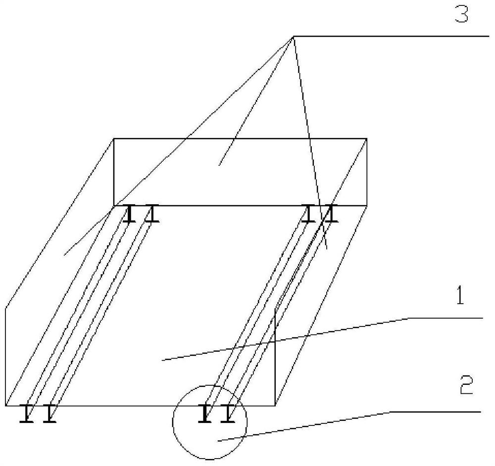
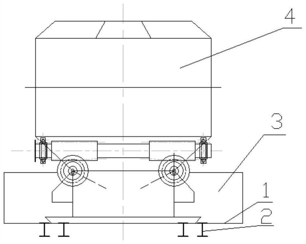
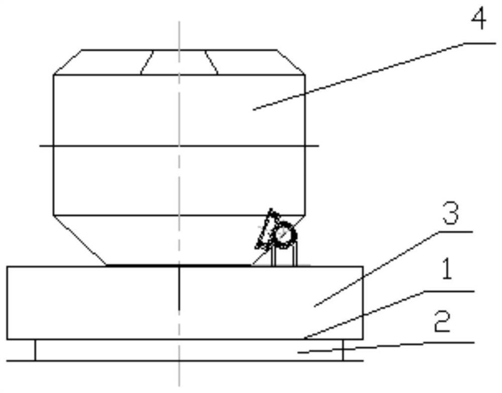
[0017] Please refer to the attached figure 1 As shown, a device for efficiently cleaning the ash tank base of the converter waste heat boiler provided by this embodiment is a device for efficiently cleaning the ash tank base of the converter waste heat boiler, including a base 1, a base support 2 and a baffle plate 3, and the base 1. Three vertical baffles 2 are set at the edge of the top surface. The baffles 2 and the base 1 enclose the top surface and an open ash cleaning space on one side. Two base supports 2 are arranged in parallel on the bottom of the base 1. The base supports 2 is composed of two I-beams arranged in parallel; the open side of the ash removal space is used as the ash removal port, the baffle plate 3 uses ordinary steel plates to block the ash, and the base 1 uses a steel plate with a thickness of 15mm; the two workers forming a single base support 2 The width between the beams is not less than the width of the fork plate of the forklift to ensure that th...


PUM

PropertyMeasurementUnit
Thicknessaaaaaaaaaa

Abstract

The invention provides equipment for efficiently removing accumulated ash on an ash tank base of a converter waste heat boiler, and belongs to the field. The equipment comprises a base, base supports and baffles, three vertical baffles are arranged on the side lines of the top face of the base, the baffles and the base define a dust removal space with the top face and one side open, the multiple base supports are arranged at the bottom of the base in parallel, and each base support is composed of two pieces of I-shaped steel arranged in parallel. The equipment is low in manufacturing cost and maintenance cost and simple in manufacturing process, after the equipment is put into use, soot around the ash tank base is effectively secondarily collected, the ash collection rate basically reaches 100%, the number of times of removing accumulated ash on the ash tank base by workers is obviously reduced, the labor intensity of the workers is reduced, and it is guaranteed that workshop production work is efficiently carried out.

Description

technical field [0001] The invention belongs to the technical field of nonferrous metallurgy, and in particular relates to a device for efficiently cleaning the ash accumulation at the base of a converter waste heat boiler ash tank. Background technique [0002] Due to the limitation of production conditions, the ash tank of the converter needs to be removed by a forklift. Because the seal between the ash tank connection port and the converter spherical flue ash discharge valve is not completely tight, soot overflow often occurs during the ash discharge process. , And then cause every time the forklift dumps the ash can, a certain amount of residual soot will accumulate around the base of the ash can. If there is a large amount of ash under the converter waste heat boiler and the spherical flue, the amount of residual soot accumulated around the ash tank will further increase, and the waste heat boiler soot contains high copper content, which has a high value for recycling, ...

Claims


Application Information

Patent Timeline
IPC IPC(8): F23J1/00F23J3/02
CPCF23J1/00F23J3/02
Inventor 王鲁博刘兴奎卢卫宁刘佳胜肖翔柴宗乾朱佳
Owner BAIYIN NONFERROUS GROUP
Learn More