
Switch socket detection device

A socket detection and switching technology, applied in the direction of electrical connection testing, etc., can solve the problems of detector looseness, looseness, and small size of the detector.

Inactive Publication Date: 2021-05-18
陈培安
View PDF0 Cites 0 Cited by
  • Summary
  • Abstract
  • Description
  • Claims
  • Application Information

AI Technical Summary

Problems solved by technology

[0004] The main purpose of the present invention is to overcome the deficiencies of the prior art and provide a switch socket detection device to solve the problem that the detector is small in size, and once the fit between the seat body and the socket body decreases, the connection of the detector will become loose and the detector will be touched As a result, the detector is loose, the installation is abnormal, the accuracy of the detection data is reduced, and there are major safety hazards. The detector is too large to be inconvenient to install.

Method used


Image

  • Switch socket detection device
  • Switch socket detection device
  • Switch socket detection device

Examples


Embodiment 1

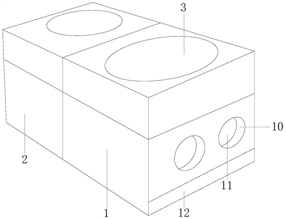
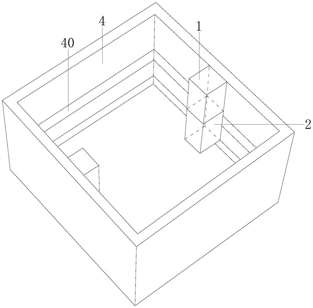
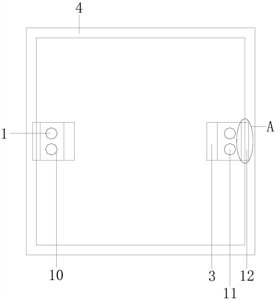
[0027] Example 1 see Figure 1-6 , the present invention provides a technical solution for switch socket detection equipment: its structure includes a detection frame 1, two detection frames 2, and an installation detector 3. The installation detector 3 is used for calorific value and smoke detection. Fire detection is also used for the separation detection of the seat body 4 and the switch board 5, the first detection frame 1 cooperates with the second detection frame 2, and the first detection frame 1 and the second detection frame 2 are equipped with a device Detector 3, said a detection frame 1 is provided with a rod hole 10, said a detection frame 1 is equipped with a displacement adjuster 11, said displacement adjuster 11 passes through the rod hole 10, said a detection frame 1 An adjustment plate 12 is installed, the first detection frame 1 and the second detection frame 2 are connected with a seat body 4, and the seat body 4 is equipped with a seat body track 40, and t...

Embodiment 2

[0029] Example 2 see Figure 7 , 8 , the present invention provides a switch socket detection equipment technical solution: the structure of the displacement adjuster 11 includes a spring 110, a shifting plate 111, a shifting device 112, an inner block 113, and a shifting rail plate 114, and the spring 110 and The shifting plate 111 is welded, and the shifting plate 111 is a retractable structure, which is convenient for the stable movement of the auxiliary shifting device 112. The shifting plate 111 is connected to the shifting device 112, and the inner block 113 is connected to the shifting rail The plate 114 is track-connected, the shifting device 112 is equipped with a local adjuster 1120, and the cover button hole 511 is a double-ring buckle structure, which not only plays a buckle role but also assists the docking of the local adjuster 1120, and the local adjustment The device 1120 includes an outer ring disc 60, an inner disc 61, and a sliding rail plate 62. The outer ...


PUM


Abstract

The invention discloses a switch socket detection device, which structurally comprises a first detection frame, a second detection frame and an installation detector. The first detection frame is matched with the second detection frame, the first detection frame and the second detection frame are provided with the installation detector, the first detection frame is provided with a rod hole, the first detection frame is provided with a displacement adjuster, the displacement adjuster passes through the rod hole. The first detection frame is provided with an adjusting plate, the first detection frame and the second detection frame are connected with a seat body, the seat body is provided with a seat body track, the seat body track is connected with the second detection frame, the adjusting plate comprises an adjusting movable plate, an adjusting fixed plate and an adjusting hole plate, and the adjusting movable plate is connected with the adjusting fixed plate track. According to the invention, the detection device and the socket body form an integrated structure, the installation size of the detector is controlled, the two movable detection frames improve the detection precision, the high fitting of the socket body and the socket body is ensured through the transmission of the displacement adjuster and the adjusting plate, and the detection precision is further ensured.

Description

technical field [0001] The invention relates to the field of detection equipment, in particular to a switch socket detection equipment. Background technique [0002] In order to improve the safety of switch sockets, fire detectors are usually installed on switch sockets. The existing electronic detection products are intelligent and miniaturized, and the detectors are generally small in size. After detecting abnormal data, an alarm will be issued to remind people. [0003] The size of the detector in the prior art is small. Once the fit between the seat body and the socket body is reduced, the connection of the detector will become loose, and the detector will be touched, resulting in loosening of the detector, abnormal installation, and a decrease in the accuracy of the detection data. Hidden danger, the larger the detector, the more difficult it is to install. Contents of the invention [0004] The main purpose of the present invention is to overcome the deficiencies of...

Claims


Application Information

Patent Timeline
IPC IPC(8): G01R31/69
CPCG01R31/69
Inventor 柳瑞林
Owner 陈培安
Learn More