High-voltage capacitance compensation cabinet capable of automatically replacing spare parts and replacement method thereof

A high-voltage capacitor and automatic replacement technology, which is applied to electrical components, circuit devices, and measurement of electrical variables, can solve problems such as untimely repairs, compensation cabinets without prompting equipment components, and affecting equipment operation.

Active Publication Date: 2021-05-18
河南省新科电控设备有限公司
View PDF3 Cites 2 Cited by
  • Summary
  • Abstract
  • Description
  • Claims
  • Application Information

AI Technical Summary

Problems solved by technology

[0003] The disadvantage of general high-voltage capacitor compensation cabinets is that when there is a problem with the compensation components in the general high-voltage capacitor compensation cabinet, the maintenance personnel can only rely on maintenance personnel to carry out maintenance in a timely manner. Since the maintenance personnel cannot guarantee that they are always near the equipment, it is easy to have emergency repairs If it is not timely, it will affect the operation of related equipment, and the general compensation cabinet does not have the function of prompting the problem of equipment components, and can only rely on the staff to check every day, and when there is a problem with the equipment, the general worker cannot know whether the problem is serious Know whether the current equipment components can continue to guarantee the relevant functions, so it is necessary to go to the site for inspection in time

Method used


Image

  • High-voltage capacitance compensation cabinet capable of automatically replacing spare parts and replacement method thereof
  • High-voltage capacitance compensation cabinet capable of automatically replacing spare parts and replacement method thereof
  • High-voltage capacitance compensation cabinet capable of automatically replacing spare parts and replacement method thereof

Examples


Embodiment Construction

[0030] The following will clearly and completely describe the technical solutions in the embodiments of the present invention with reference to the accompanying drawings in the embodiments of the present invention. Obviously, the described embodiments are only some, not all, embodiments of the present invention. Based on the embodiments of the present invention, all other embodiments obtained by persons of ordinary skill in the art without making creative efforts belong to the protection scope of the present invention.

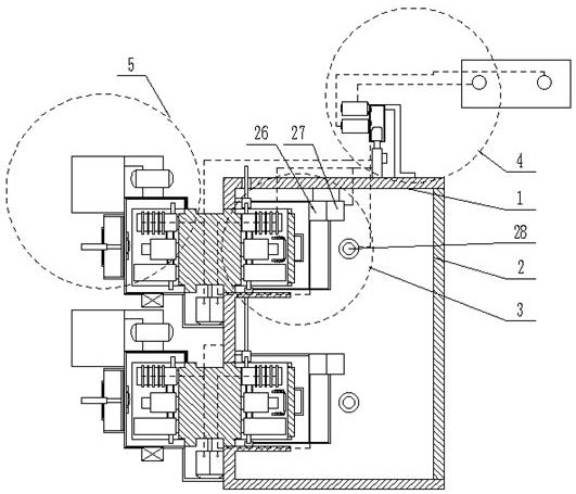
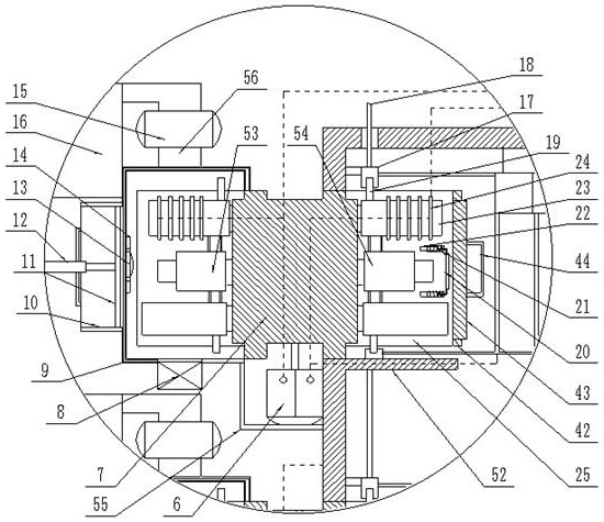
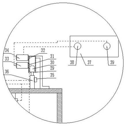
[0031] see Figure 1-9 , the present invention provides a technical solution: a high-voltage capacitor compensation cabinet for automatic replacement of spare parts, including a cabinet body 1, a cabinet door 2 is provided on the right side of the cabinet body 1, and a rotating The replacement mechanism 3, the rotation replacement mechanism 3 is equidistantly distributed along the cabinet body 1 from top to bottom, the rotation replacement mechanism 3 includes...


PUM


Abstract

The invention discloses a high-voltage capacitance compensation cabinet capable of automatically replacing spare parts and a replacement method thereof. The compensation cabinet comprises a cabinet body, a cabinet door is arranged on the right side of the cabinet body, a rotary replacement mechanism is arranged on a left side plate of the cabinet body, and the rotary replacement mechanism comprises a stepping motor, a rotary column and a first capacitance compensation assembly, a second capacitance compensation assembly, a first U-shaped embedding groove, a U-shaped connecting frame, a conductive column, a U-shaped conductive frame, a rubber ring, a pressure sensing switch, a voltage sensor, a current sensor and a signal transmitting mechanism. When the voltage sensor and the current sensor detect that the current and the voltage of the first capacitance compensation assembly deviate from normal values or the pressure sensing switch on the capacitor is pressed, the stepping motor drives the first capacitance compensation assembly and the second capacitance compensation assembly on the left side and the right side to rotate and exchange positions; therefore, the second capacitance compensation assembly replaces the first capacitance compensation assembly to be connected to the circuit, and automatic replacement is achieved.

Description

technical field [0001] The invention relates to the technical field of high-voltage capacitor compensation cabinets, in particular to a high-voltage capacitor compensation cabinet for automatically replacing spare parts and a replacement method thereof. Background technique [0002] The components in the high-voltage capacitor compensation cabinet are mainly used in the power system to improve the power factor, adjust the voltage, and reduce the loss of the power grid. The components in the high-voltage capacitor compensation cabinet are generally grouped and neatly arranged in the cabinet; [0003] The disadvantage of the general high-voltage capacitor compensation cabinet is that when there is a problem with the compensation components in the general high-voltage capacitor compensation cabinet, the maintenance personnel can only rely on the maintenance personnel to repair it in time. Since the maintenance personnel cannot guarantee that they are always near the equipment, r...

Claims


Application Information

Patent Timeline
Patent Type & Authority Applications(China)
IPC IPC(8): H02B1/32H02B3/00H02J13/00G01R19/00
CPCH02B1/32H02B3/00H02J13/00002G01R19/00
Inventor 彭涛
Owner 河南省新科电控设备有限公司
Why Eureka
Try Eureka