
WIFI radio frequency test system and method

A radio frequency test system and parametric test technology, applied in transmitter monitoring, receiver monitoring and other directions, can solve the problems of low test efficiency, low cost, poor test stability and so on

Pending Publication Date: 2021-05-18
SHENZHEN WELLTEST TECH CO LTD
View PDF6 Cites 3 Cited by
  • Summary
  • Abstract
  • Description
  • Claims
  • Application Information

AI Technical Summary

Problems solved by technology

The existing test equipment is low in cost, poor in test stability, and slow in test speed, resulting in low test efficiency

Method used


Image

  • WIFI radio frequency test system and method
  • WIFI radio frequency test system and method
  • WIFI radio frequency test system and method

Examples


Embodiment approach

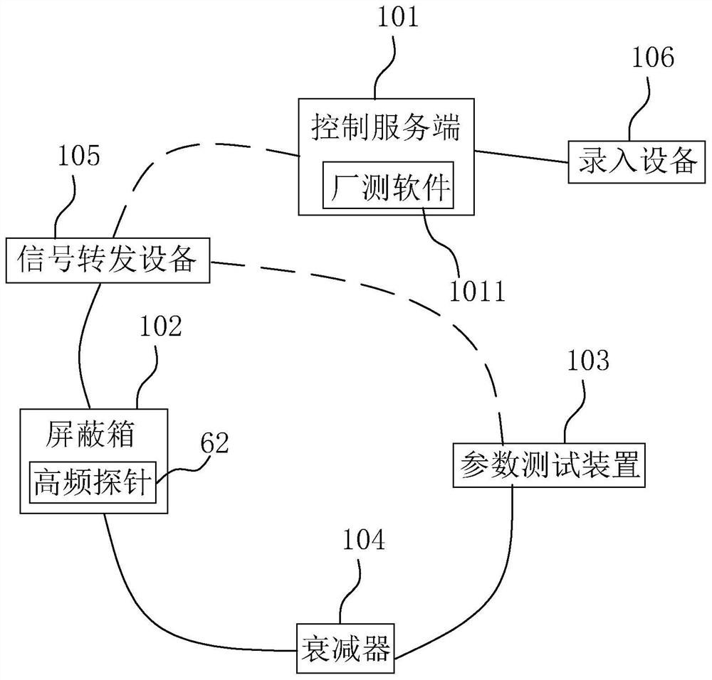
[0090] refer to Figure 7 , as an implementation of the test access wiring 202, including the following steps:

[0091] 2021. Connect one end of the serial cable to the input and output interface of the product under test, and connect the other end to the input and output port of the signal forwarding device.

[0092] 2022. Connect one end of the attenuator to the high-frequency probe through a radio frequency cable, and connect the other end of the attenuator to an output end of the parameter testing device through a radio frequency cable.

[0093] 2023. Start the third cylinder to make the high-frequency probe approach and connect to the RF head of the product under test.

[0094] refer to Figure 8 , as an implementation of launch indicator debugging 203, including the following steps:

[0095] 2031. In the first step of updating the calibration file, the calibration file is updated and placed in the project directory of the factory test software at the control server. ...


PUM


Abstract

The invention relates to a WIFI radio frequency test system and method, and belongs to the field of automatic test technology, the test system comprises a control server, a shielding box, a parameter test device, an attenuator and a high frequency probe; the parameter test device is used for measuring an emission index of an emission signal of a tested product and outputting a second signal; the control server is provided with factory test software; the input end of the attenuator is connected with the high-frequency probe through a radio frequency cable; the high-frequency probe is arranged in the shielding box and is used for being connected with an RF head of the tested product; the shielding box is used for bearing the tested product; and based on the test system, the invention provides the WIFI radio frequency test method. Compared with the prior art, the method and the device have the effect of improving the test efficiency under the condition of ensuring relatively low cost.

Description

technical field [0001] The present application relates to the field of automatic test technology, in particular to a WIFI radio frequency test system and method. Background technique [0002] With the rapid development of mobile communication technology, the coverage of wireless networks is getting wider and wider. At the same time, with the popularization of various wireless network products, consumer electronic products such as mobile phones, tablets, stereos, notebook computers, and sweeping machines have gradually become popular among people. An essential part of life. People's demand for consumer electronic products is increasing, and the demand drives development and production. The products on the electronic product production line are constantly updated, which means that the tooth equipment used in the production line is also facing the need for replacement. [0003] Consumer electronic products have more and more functions, and the performance requirements for the ...

Claims


Application Information

Patent Timeline
Patent Type & Authority Applications(China)
IPC IPC(8): H04B17/15H04B17/11H04B17/29H04B17/21
CPCH04B17/15H04B17/11H04B17/29H04B17/21
Inventor 余守军
Owner SHENZHEN WELLTEST TECH CO LTD
Learn More