Supercharge Your Innovation With Domain-Expert AI Agents!

Automatic lattice bar feeding device

A grid, automatic technology, used in transportation and packaging, conveyor objects, conveyors, etc., can solve problems such as inability to achieve automation, low production efficiency, and large labor costs.

Active Publication Date: 2021-05-25
佛山市法比澳挤压机械科技有限公司
View PDF6 Cites 0 Cited by
  • Summary
  • Abstract
  • Description
  • Claims
  • Application Information

AI Technical Summary

Problems solved by technology

However, it requires a lot of labor costs, cannot be automated, and has low production efficiency

Method used


Image

  • Automatic lattice bar feeding device
  • Automatic lattice bar feeding device
  • Automatic lattice bar feeding device

Examples


Embodiment Construction

[0025] Embodiments of the present invention are described in detail below, examples of which are shown in the drawings, wherein the same or similar reference numerals designate the same or similar elements or elements having the same or similar functions throughout. The embodiments described below by referring to the figures are exemplary only for explaining the present invention and should not be construed as limiting the present invention.

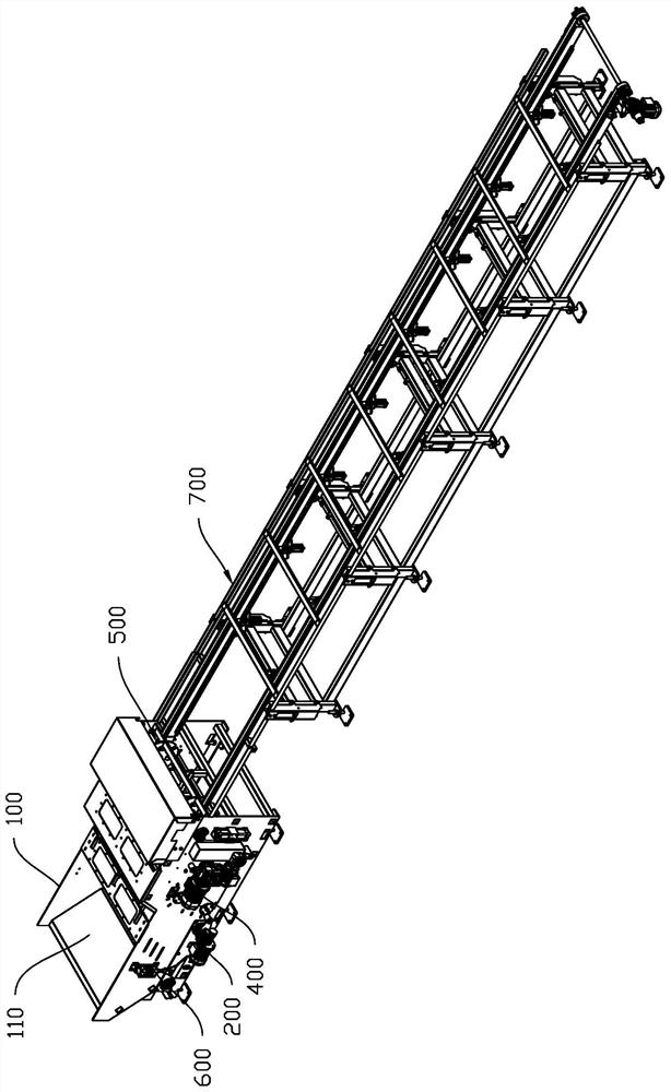
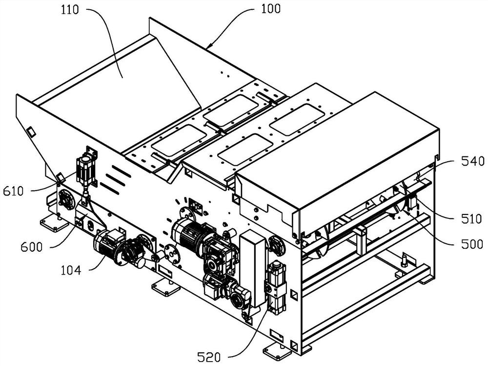
[0026] refer to figure 1 , 3 , shown in 4, a kind of automatic upper grid bar device, comprises fuselage 100, lower conveyor belt 200, lifting device 300, upper conveyor belt 400, rotating material distribution mechanism 500; Body 100 top is provided with grid bar inlet 110; The belt 101 is installed at the bottom of the inner cavity of the fuselage 100, and the conveyor belt 101 is located under the grid inlet 110; the lifting device 300 is located at the end of the conveying stroke of the lower conveyor belt 200; the upper conveyor be...


PUM


Abstract

The invention discloses an automatic lattice bar feeding device. The automatic lattice bar feeding device comprises a machine body, a lower conveying belt, an ascending device, an upper conveying belt and a rotary distributing mechanism. A lattice bar inlet is formed in the top of the machine body; the conveying belt is arranged at the bottom of the inner cavity of the machine body and is positioned below the lattice bar inlet; the ascending device is located at the end point of the conveying stroke of the lower conveying belt; the upper conveying belt is located at the end point of the ascending stroke of the ascending device; the rotary distributing mechanism is located at the end point of the stroke of the upper conveying belt; and lattice bars are placed in from the lattice bar inlet in the machine body, conveyed to the ascending device through the lower conveying belt and conveyed to the upper conveying belt through the ascending device, the lattice bars are distributed through the rotary distributing mechanism, the lattice bars can be automatically and evenly distributed to the designated positions, and important links and lattice bar distribution work in an automatic loading system are completed.

Description

technical field [0001] The invention relates to the technical field of production equipment, in particular to a feed dryer. Background technique [0002] Traditionally, the grids are manually loaded, and then automatically transported by machinery to the bottom of the aluminum material for picking and conveying, and for material distribution and conveying. However, it requires a lot of labor costs, cannot be automated, and has low production efficiency. Contents of the invention [0003] The present invention aims to solve at least one of the technical problems existing in the prior art. For this reason, the present invention proposes a kind of automatic upper lattice bar device, comprises fuselage, lower conveyer belt, lifting device, upper conveyer belt, rotating material distribution mechanism; Described fuselage top is provided with lattice bar entrance; Described lower conveyer belt Installed at the bottom of the inner cavity of the fuselage, the conveyor belt is lo...

Claims


Application Information

Patent Timeline
Patent Type & Authority Applications(China)
IPC IPC(8): B65G47/52B65G23/04
CPCB65G47/52B65G23/04Y02E60/10
Inventor 傅昌明邓孟齐文龙陈玉山付明明
Owner 佛山市法比澳挤压机械科技有限公司
Features
  • R&D
  • Intellectual Property
  • Life Sciences
  • Materials
  • Tech Scout
  • Unparalleled Data Quality
  • Higher Quality Content
  • 60% Fewer Hallucinations
Learn More