Thread pair capable of preventing automatic rolling movement in loosening direction

A thread pair, automatic technology, applied in the field of thread pair, can solve the problem that it is difficult to control the clamping force of the workpiece, and achieve the effect of easy control

Pending Publication Date: 2021-05-25
许松林
View PDF1 Cites 1 Cited by
  • Summary
  • Abstract
  • Description
  • Claims
  • Application Information

AI Technical Summary

Problems solved by technology

[0005] The technical scheme of "Double Nut Threaded Connection to Prevent Automatic Rolling Movement in the Loosening Direction" with the notification number CN208252561U designed by the inventor has the following disadvantages: at the same time, the connection between the upper flank of the internal thread of the second nut and the lower flank of the external thread of the bolt is realized. The structure of mutual contact between the lower flank of the internal thread of the first nut and the upper flank of the outer thread of the bolt can effectively prevent the contact between the first nut, the second nut and the bolt during lateral vibration or impact. Continuous rolling motion in the loosening direction, that is, the axial force on the top of the first nut is greater than the initial clamping force, in order to effectively prevent the continuous movement between the first nut, the second nut and the bolt during lateral vibration or impact. Therefore, it is difficult to control the clamping force on the workpiece when implementing this technical solution

Method used


Image

  • Thread pair capable of preventing automatic rolling movement in loosening direction
  • Thread pair capable of preventing automatic rolling movement in loosening direction
  • Thread pair capable of preventing automatic rolling movement in loosening direction

Examples


Embodiment 1

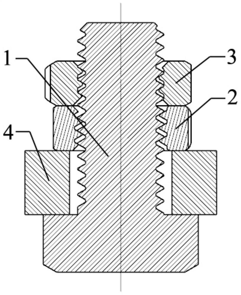
[0033] Such as figure 1 As shown, the thread pair that prevents the automatic rolling movement in the loosening direction includes a bolt 1, a first nut 2 and a second nut 3, and the major diameter of the internal thread of the second nut 3 is smaller than the major diameter of the external thread of the bolt 1. After the bolt 1, the first nut 2 and the second nut 3 are installed and tightened on the workpiece 4, the bottom of the first nut 2 is in contact with the workpiece 4, and the bottom of the second nut 3 is in contact with the first The top of the nut 2 is in contact with each other. The bottom of the internal thread of the second nut 3 and the crest of the external thread of the bolt 1 are in a mutual laterally locked contact structure. The upper flank of the internal thread of the first nut 2 is in contact with the The structure in which the lower flanks of the external thread of the bolt 1 are in contact with each other, the structure in which the upper flank of the...

Embodiment 2

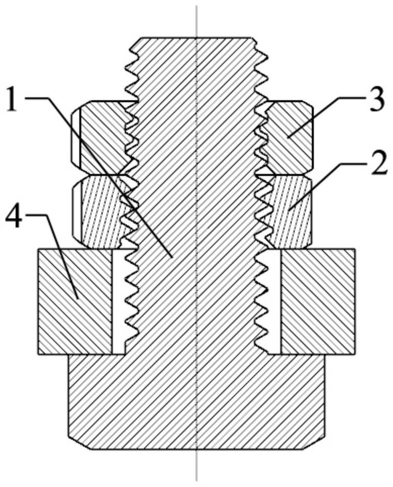
[0037] Such as figure 2 As shown, the thread pair that prevents the automatic rolling movement in the loosening direction includes a bolt 1, a first nut 2 and a second nut 3, and the major diameter of the internal thread of the second nut 3 is smaller than the major diameter of the external thread of the bolt 1. After the bolt 1, the first nut 2 and the second nut 3 are installed and tightened on the workpiece 4, the bottom of the first nut 2 is in contact with the workpiece 4, and the bottom of the second nut 3 is in contact with the first The top of the nut 2 is in contact, the bottom of the internal thread of the second nut 3 and the crest of the external thread of the bolt 1 are mutually locked in a contact structure, the lower flank of the internal thread of the first nut 2 is in contact with the crest of the external thread of the bolt 1 The structure in which the upper flanks of the external thread of the bolt 1 are in contact with each other, the structure in which th...

Embodiment 3

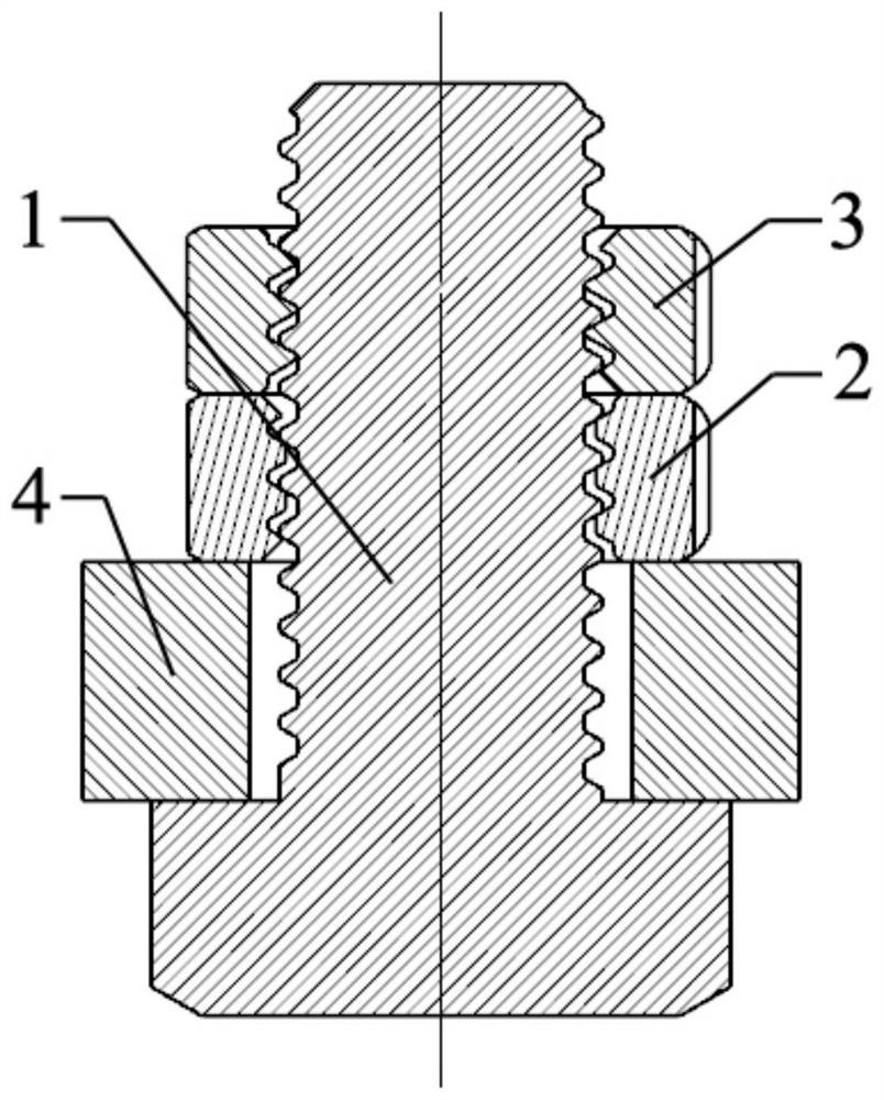
[0041] Such as image 3 As shown, the thread pair that prevents the automatic rolling movement in the loosening direction includes a bolt 1, a first nut 2 and a second nut 3, the inner thread minor diameter of the second nut 3 is smaller than the outer thread minor diameter of the bolt 1, and the After the bolt 1, the first nut 2 and the second nut 3 are installed and tightened on the workpiece 4, the bottom of the first nut 2 is in contact with the workpiece 4, and the bottom of the second nut 3 is in contact with the first nut 2. The crest of the internal thread of the second nut 3 and the bottom of the external thread of the bolt 1 are mutually locked in a contact structure, and the upper flank of the internal thread of the first nut 2 is in contact with the bottom of the external thread of the bolt 1. The structure in which the lower flanks of the external thread of the bolt 1 are in contact with each other, the structure in which the upper flank of the internal thread of ...


PUM


Abstract

The invention discloses a thread pair capable of preventing automatic rolling movement in a loosening direction. The thread pair capable of preventing the automatic rolling movement in the loosening direction comprises a bolt, a first nut and a second nut, wherein the major diameter of the internal thread of the second nut is less than the major diameter of the external thread of the bolt, or the minor diameter of the internal thread of the second nut is less than the minor diameter of the external thread of the bolt; after the bolt, the first nut and the second nut are installed and screwed on a workpiece, the bottom of the first nut makes contact with the workpiece, the bottom of the second nut makes contact with the top of the first nut, and the tooth bottom of the internal thread of the second nut and the tooth top of the external thread of the bolt are of contact structures which are transversally locked with each other; or the tooth top of the internal thread of the second nut and the tooth bottom of the external thread of the bolt are of contact structures which are transversally locked with each other, so that the first nut, the second nut and the bolt can be effectively prevented from continuous rolling movement in the loosening direction during transverse vibration or impact.

Description

technical field [0001] The invention relates to the field of fasteners, in particular to a thread pair that prevents automatic rolling motion in the loosening direction. Background technique [0002] Objectively, there are sliding motion (for example, under the action of rotational inertia, the internal thread will slide and rotate in the direction of relative loosening) and rolling motion ( No fixed axis lateral rotation movement) these two ways. [0003] In the published article "New Anti-loosening Principle and Anti-loosening Technology of Cylindrical Thread Connection" [China New Technology and New Products, 2015.10 (Part 1)], the inventor used theoretical analysis and experimental results to prove that "cylindrical thread connection can The looseness generated in the impact environment is the non-fixed axis lateral rotation motion (rolling motion) between the internal and external threaded parts. Therefore, as long as the lateral locking between the internal and extern...

Claims


Application Information

Patent Timeline
Patent Type & Authority Applications(China)
IPC IPC(8): F16B39/28F16B37/00
CPCF16B37/00F16B39/28
Inventor 许松林
Owner 许松林
Why Eureka
Try Eureka