New gate valve and gate valve assembly method

A gate valve, a new type of technology, applied in valve devices, valve details, sliding valves, etc., can solve the problems of easy loosening of bolts and nuts, strengthen the limiting function of the positioning ring, etc., to achieve strong limiting ability, and enhance reliability. shedding effect

Active Publication Date: 2022-02-11
ANHUI REDSTAR VALVE
View PDF0 Cites 0 Cited by
  • Summary
  • Abstract
  • Description
  • Claims
  • Application Information

AI Technical Summary

Problems solved by technology

[0006] With such a setting, the positioning ring and the limiting structure can axially limit the valve stem, and the positioning ring hoop valve stem solves the problem of easy loosening when bolts and nuts are used. The positioning ring hoop valve stem can be Drive the positioning ring to rotate together to strengthen the positioning ring's limiting effect on the valve stem; moreover, the positioning ring and the limiting structure's limiting force on the valve stem are all applied to the valve cover, which is larger and fixed to the valve body connection, which can strengthen the reliability of the positioning ring and the limit structure for the limit of the valve stem

Method used


Image

  • New gate valve and gate valve assembly method
  • New gate valve and gate valve assembly method
  • New gate valve and gate valve assembly method

Examples


Embodiment 1

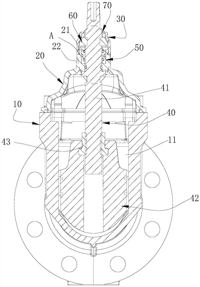
[0062] See figure 1 and figure 2 , the new gate valve 100 also includes a sealing letter 50 , the sealing letter 50 is arranged inside the valve cover 20 and sleeved outside the valve stem 41 for sealing connection between the valve stem 41 and the valve cover 20 . The sealing letter 50 is made of rigid materials such as stainless steel.

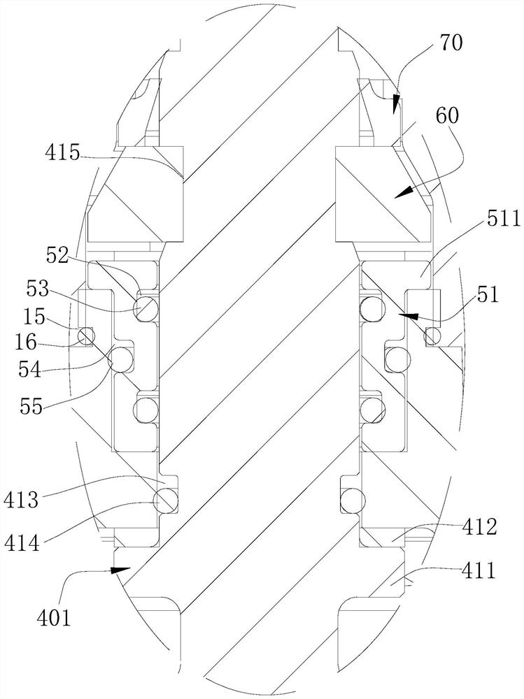
[0063] The sealing letter 50 is provided with a first matching portion 51 , and the valve cover 20 is provided with a first limiting portion 23 , the cooperation between the first matching portion 51 and the first limiting portion 23 can position and install the sealing letter 50 on the valve cover 20 Inside.

[0064] In this embodiment, the first fitting part 51 is a boss 511, and the boss 511 is arranged on the end of the sealing letter 50 away from the valve flap 42, and the first limiting part 23 is a limiting groove 231, and the limiting groove 231 is opened on the second On the end surface of the first section 21 away from the seco...

Embodiment 2

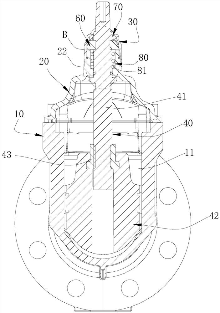
[0082] See image 3 and Figure 4 , the structure of this embodiment is basically the same as that of Embodiment 1, and the similarities will not be repeated, and the difference is:

[0083] The envelope 80 is used to replace the sealing letter 50. There are multiple envelopes 80, and the plurality of envelopes 80 are arranged outside the valve stem 41 at intervals. The fifth sealing member 81 is arranged between adjacent envelopes 80, and the envelope 80 is close to the position of the positioning ring 60. The end surface of one end abuts against the positioning ring 60 . The envelope 80 is made of flexible materials such as plastics and rubber.

[0084] When the valve stem 41 is rotated counterclockwise, since the sleeve 80 is separated from the sleeve 80 by the fifth sealing member 81, and there is an extrusion space in the middle, the valve stem 41 moves toward the direction of the valve disc 42, and the positioning ring 60 can be squeezed. The envelope 80 releases the ...


PUM


Abstract

The invention relates to the technical field of valves, in particular to a novel gate valve and an assembly method for the gate valve. A new type of gate valve, comprising a valve body, a valve cover, a sheath and a valve core assembly, the sheath is arranged on the valve cover, the valve cover is arranged on the valve body, the valve body has a valve cavity, The valve body is provided with a first port and a second port, and the valve core assembly is passed through the sheath and the bonnet and extends into the valve cavity and can be moved along the valve core assembly. Axial movement to control the communication or isolation between the first port and the second port; the new gate valve also includes a positioning ring, the valve core assembly includes a valve stem, and the valve stem is provided with a limiting structure, The locating ring hoops the valve stem, one end of the locating ring abuts against the bonnet, and the limiting structure is arranged in the valve chamber and can cooperate with the inner wall of the bonnet to control the bonnet. The valve stem is axially limited. The advantage of the present invention is that it can strengthen the reliability of the position limitation of the valve stem.

Description

technical field [0001] The invention relates to the technical field of valves, in particular to a novel gate valve and an assembly method for the gate valve. Background technique [0002] The gate valve is installed on the water delivery pipeline system and plays the role of opening and closing. The gate valve includes a valve core assembly, and the valve core assembly includes a valve stem. The opening and closing of the gate valve is realized by rotating the valve stem. [0003] In the patent application No. 2013107451074, the valve stem jacket is provided with a lock nut, and then a positioning bolt is screwed into the lock nut from the outside, and the positioning bolt is pressed against the valve stem to realize the limit of the valve stem, and the positioning bolt and the valve stem It is not connected, and its resistance is poor, and the positioning bolt is prone to loosening in the lock nut, which affects the reliability of the position limit of the valve stem, and t...

Claims


Application Information

Patent Timeline
Patent Type & Authority Patents(China)
IPC IPC(8): F16K3/02F16K3/314F16K27/04F16K27/08
CPCF16K3/0218F16K3/314F16K27/044F16K27/08
Inventor 孙世林钟应武査从瑞
Owner ANHUI REDSTAR VALVE
Why Eureka
Try Eureka