A machine tool limit base

A technology of machine tools and threaded holes, which is applied in the direction of metal processing machinery parts, metal processing equipment, maintenance and safety accessories, etc., can solve the problems of inconvenient installation of machine tool limit equipment, inability to ensure accurate position, inconvenient operation of personnel, etc., and achieve saving The effect of installation adjustment time, strong limit effect and simple structure

Active Publication Date: 2018-10-12
威海德尔瑞通科技信息有限公司 +1
View PDF6 Cites 0 Cited by
  • Summary
  • Abstract
  • Description
  • Claims
  • Application Information

AI Technical Summary

Problems solved by technology

[0002] With the rapid development of science and technology, more and more industries have realized mechanization and automation. Various processing machine tools are widely used in the processing of various products. In machine tool equipment, the base is a very important part. When processing parts, the base will be subjected to a large force. Therefore, the stability of the base needs to be ensured to prevent the base from shifting during part processing. The base of the machine tool must bear the weight of itself and all parts on it, which is the overall The basis for the stable operation of the machine tool. Its strength and rigidity are crucial to ensure the accuracy of the entire large-scale equipment. The base is used as the supporting device for the machine tool equipment. In the existing base equipment, during the installation process of the machine tool, the position of the machine tool must be manually adjusted due to the weight of the equipment. It is time-consuming and cannot guarantee the accuracy of the position. The existing machine tool limit equipment is inconvenient to install and inconvenient for personnel to operate

Method used


Image

  • A machine tool limit base
  • A machine tool limit base
  • A machine tool limit base

Examples


Embodiment Construction

[0016] The technical solutions in the embodiments of the present invention will be clearly and completely described below in conjunction with the accompanying drawings in the embodiments of the present invention. Obviously, the described embodiments are only some of the embodiments of the present invention, not all of them. Based on The embodiments of the present invention and all other embodiments obtained by persons of ordinary skill in the art without making creative efforts belong to the protection scope of the present invention.

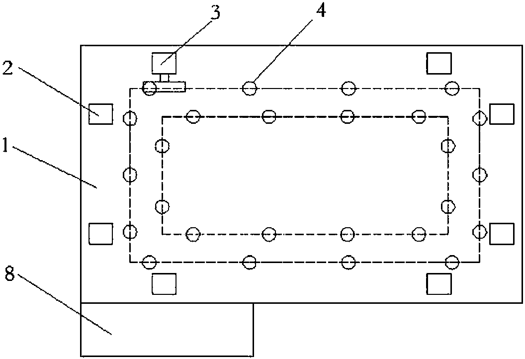
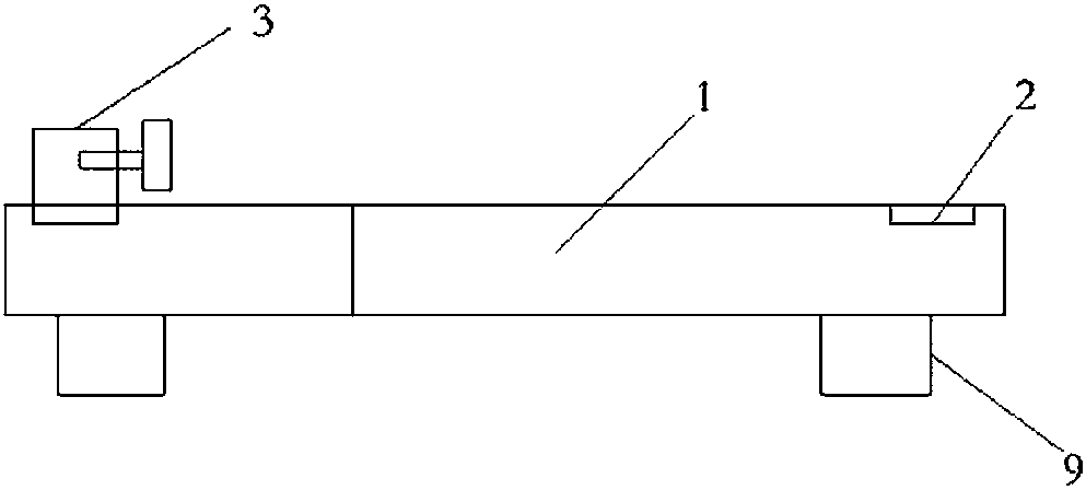
[0017] see figure 1 , 2 , 3, 4, a machine tool limit base, including a base 1, the top of the base 1 is provided with a plurality of square grooves 2, and the top of the square groove 2 is provided with a hydraulic pusher 3, and the hydraulic pusher 3 is placed in the square groove 2. When adjusting the position of the machine tool, the position of the machine tool is adjusted through multiple hydraulic push devices 3. After the adjustment is c...


PUM


Abstract

The invention relates to a limiting base of a machine tool, comprising a base body. A plurality of square grooves are formed in the side of the base body top. A hydraulic thrust unit is arranged on the top of the square grooves. One side of each square groove is provided with multiple rectangular-distributed threaded holes. Each threaded hole is provided with a lead screw, and both the top and the bottom of each lead screw are connected with bolts. The top outer ring of each lead screw is connected with a fixing plate and the fixing plate sleeves on the top bolt. One side of the base body is provided with a lifting platform, and the bottom of the base body is provided with multiple supporting legs. The device can quickly adjust the position of the machine tool when the machine tool is loaded on the base body initially and save the installation and adjustment time of the machine tool. The limiting base of the machine tool is simple in design, convenient to operate, capable of quickly adjusting the machine tool, strong in limiting effect through the fixing plates, capable of effectively reducing machine tool displacement due to shaking during operation and ensuring the fixed position of the machine tool, simple in structure and strong in practicability.

Description

technical field [0001] The invention relates to a position limiting base of a machine tool. Background technique [0002] With the rapid development of science and technology, more and more industries have realized mechanization and automation. Various processing machine tools are widely used in the processing of various products. In machine tool equipment, the base is a very important part. When processing parts, the base will be subjected to a large force. Therefore, the stability of the base needs to be ensured to prevent the base from shifting during part processing. The base of the machine tool must bear the weight of itself and all parts on it, which is the overall The basis for the stable operation of the machine tool. Its strength and rigidity are crucial to ensure the accuracy of the entire large-scale equipment. The base is used as the supporting device for the machine tool equipment. In the existing base equipment, during the installation process of the machine to...

Claims


Application Information

Patent Timeline
Patent Type & Authority Patents(China)
IPC IPC(8): B23Q1/01B23Q11/00
CPCB23Q1/015B23Q11/00
Inventor 蒋伟
Owner 威海德尔瑞通科技信息有限公司
Why Eureka
Try Eureka