Automatic seeding equipment
A kind of equipment and automatic technology, applied in the direction of sowing, planter parts, applications, etc., can solve the problems of manpower consumption, easy sticking of seeds to containers, and inability to irrigate in time, so as to avoid seed blockage, facilitate movement and fix equipment
- Summary
- Abstract
- Description
- Claims
- Application Information
AI Technical Summary
Problems solved by technology
Method used
Image
Examples
Embodiment 1
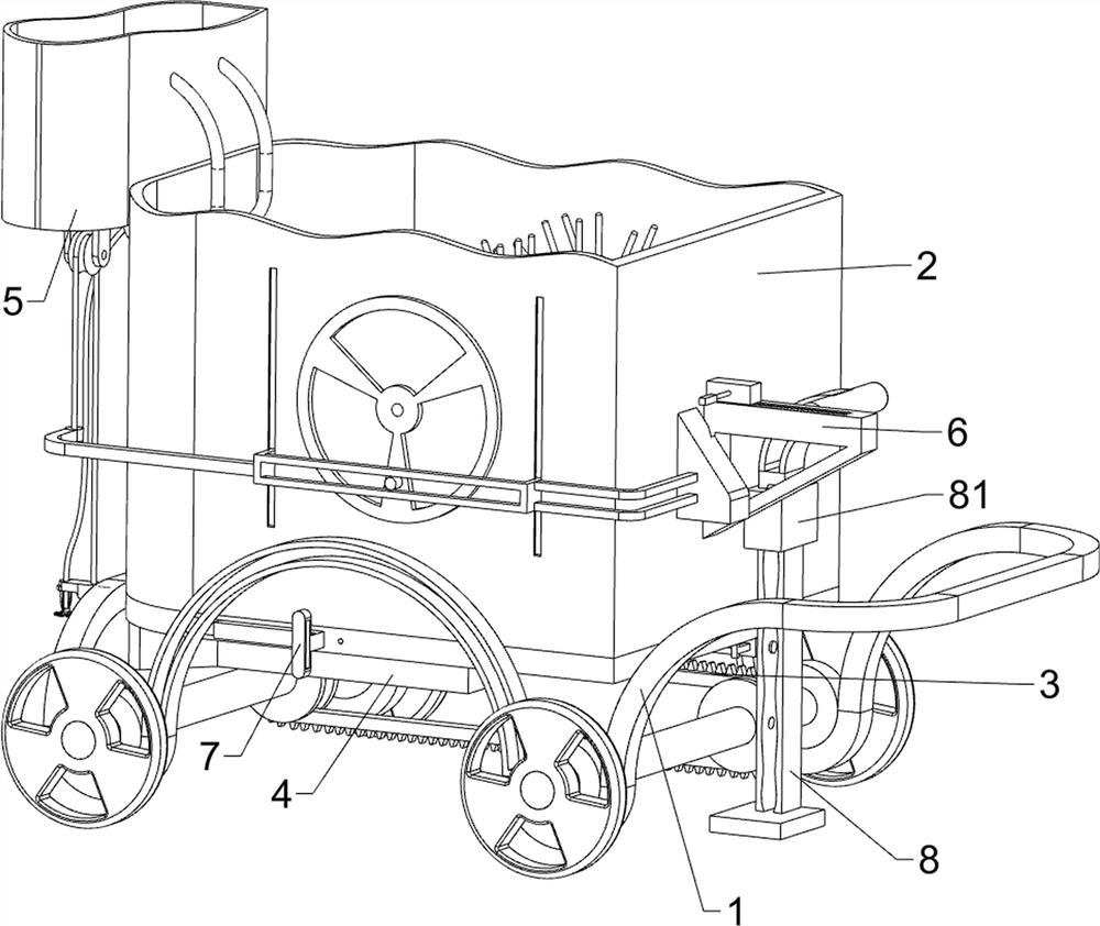
[0031] An automatic seeding device such as figure 1 , figure 2 , image 3 and Figure 4 As shown, it includes a vehicle frame 1, a casing 2, a rotating mechanism 3 and a pushing mechanism 4. A casing 2 is connected between the left side of the upper part of the vehicle frame 1 and the front and rear sides, and a rotating mechanism is provided between the bottom of the vehicle frame 1 and the casing 2. Mechanism 3, a pushing mechanism 4 is arranged between the lower part of the casing 2 and the rotating mechanism 3 .
[0032]The rotating mechanism 3 includes a first rotating shaft 31, a wheel 32, a first transmission group 33, a second rotating shaft 34, a gear 35, a third rotating shaft 36, a second transmission group 37, a rotating rod 38 and a rotating rack 39, The first rotating shaft 31 is connected symmetrically between the front and rear sides of the lower part of the vehicle frame 1, the front and rear ends of the first rotating shaft 31 are connected with wheels 32...
Embodiment 2
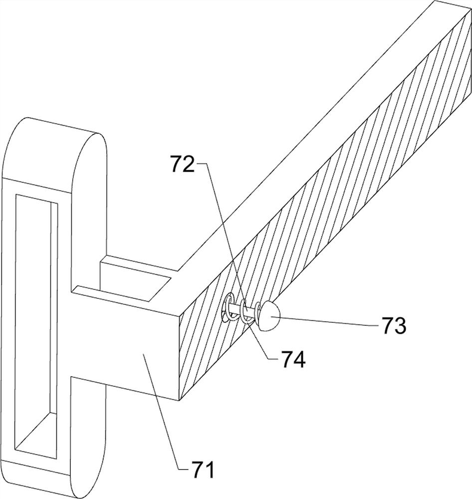
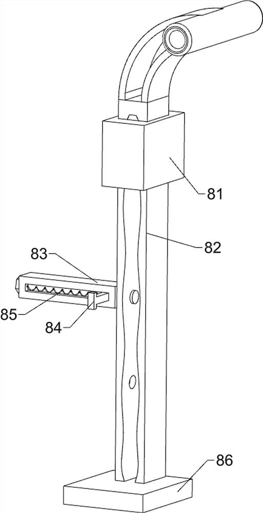
[0036] On the basis of Example 1, such as figure 1 , Figure 5 , Figure 6 , Figure 7 , Figure 8 and Figure 9 Shown, also includes sprinkling assembly 5, and sprinkling assembly 5 includes support rod 51, water storage tank 52, rotating disk 53, the 3rd connecting rod 54, the first sliding rod 55, fixed rod 56, pulley 57, connection wire 58, conduit 59. The first slider 510, the third spring 511 and the sprinkler head 512. The upper left side of the casing 2 is symmetrically connected with a support rod 51 front and rear, and a water storage tank 52 is connected between the left side of the support rod 51. There is a turntable 53, the turntable 53 is located on the outer side of the casing 2, a third connecting rod 54 is connected in the middle of the lower front side of the turntable 53, and a first slide bar 55 is slidably connected between the left and right sides of the front part of the casing 2, and the first slide bar 55 is connected to the front side of the casi...
PUM
 Abstract
Description
Claims
Application Information
 - R&D
- Intellectual Property
- Life Sciences
- Materials
- Tech Scout
- Unparalleled Data Quality
- Higher Quality Content
- 60% Fewer Hallucinations
Browse by: Latest US Patents, China's latest patents, Technical Efficacy Thesaurus, Application Domain, Technology Topic, Popular Technical Reports.
© 2025 PatSnap. All rights reserved.Legal|Privacy policy|Modern Slavery Act Transparency Statement|Sitemap|About US| Contact US: help@patsnap.com


