
Automatic pipeline purging system and method

An automatic and pipeline technology, applied in the field of machinery, can solve the problems of inconvenient operation, time-consuming pipeline, frequent pipeline cleaning, etc., and achieve the effect of easy cleaning in the later stage, convenient blowing operation, and good blowing effect

Inactive Publication Date: 2021-05-28
SHENZHEN CHA ZHI TECH
View PDF8 Cites 2 Cited by
  • Summary
  • Abstract
  • Description
  • Claims
  • Application Information

AI Technical Summary

Problems solved by technology

[0002] The sampling pipe of the aspirating smoke detection device is generally made of PVC pipe, and the sampling hole on the sampling pipe is generally 2-3mm. These small holes are easily blocked by foreign matter such as dust, water droplets, fibers, insects, etc. The device cannot collect the air in the protected area, resulting in its function failure, especially in places with relatively large dust, this phenomenon occurs more frequently
[0003] In order to solve the problem of blockage of the sampling hole, the pipeline is generally cleaned manually, especially when the aspirating smoke detection device is installed in the high altitude, in the interlayer, on the upper part of the ceiling, etc., the frequent cleaning of the pipeline will bring greater damage Difficult, so manually cleaning the sampling pipeline is time-consuming, labor-intensive, and inconvenient to operate.
[0004] The invention solves the problems of cumbersome manual operation, dangerous high-pressure operation and high cost

Method used


Image

  • Automatic pipeline purging system and method
  • Automatic pipeline purging system and method
  • Automatic pipeline purging system and method

Examples


Embodiment Construction

[0041] In order to make the above objects, features and advantages of the present invention more comprehensible, specific implementations of the present invention will be described in detail below in conjunction with the accompanying drawings. In the following description, numerous specific details are set forth in order to provide a thorough understanding of the present invention. However, the present invention can be implemented in many other ways different from those described here, and those skilled in the art can make similar improvements without departing from the connotation of the present invention, so the present invention is not limited by the specific implementations disclosed below.

[0042] It should be noted that when an element is referred to as being “fixed” to another element, it can be directly on the other element or there can also be an intervening element. When an element is referred to as being "connected to" another element, it can be directly connected ...


PUM


Abstract

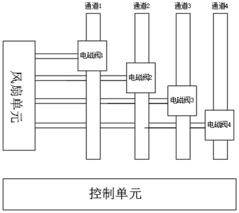
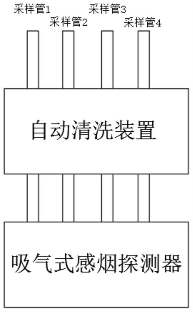
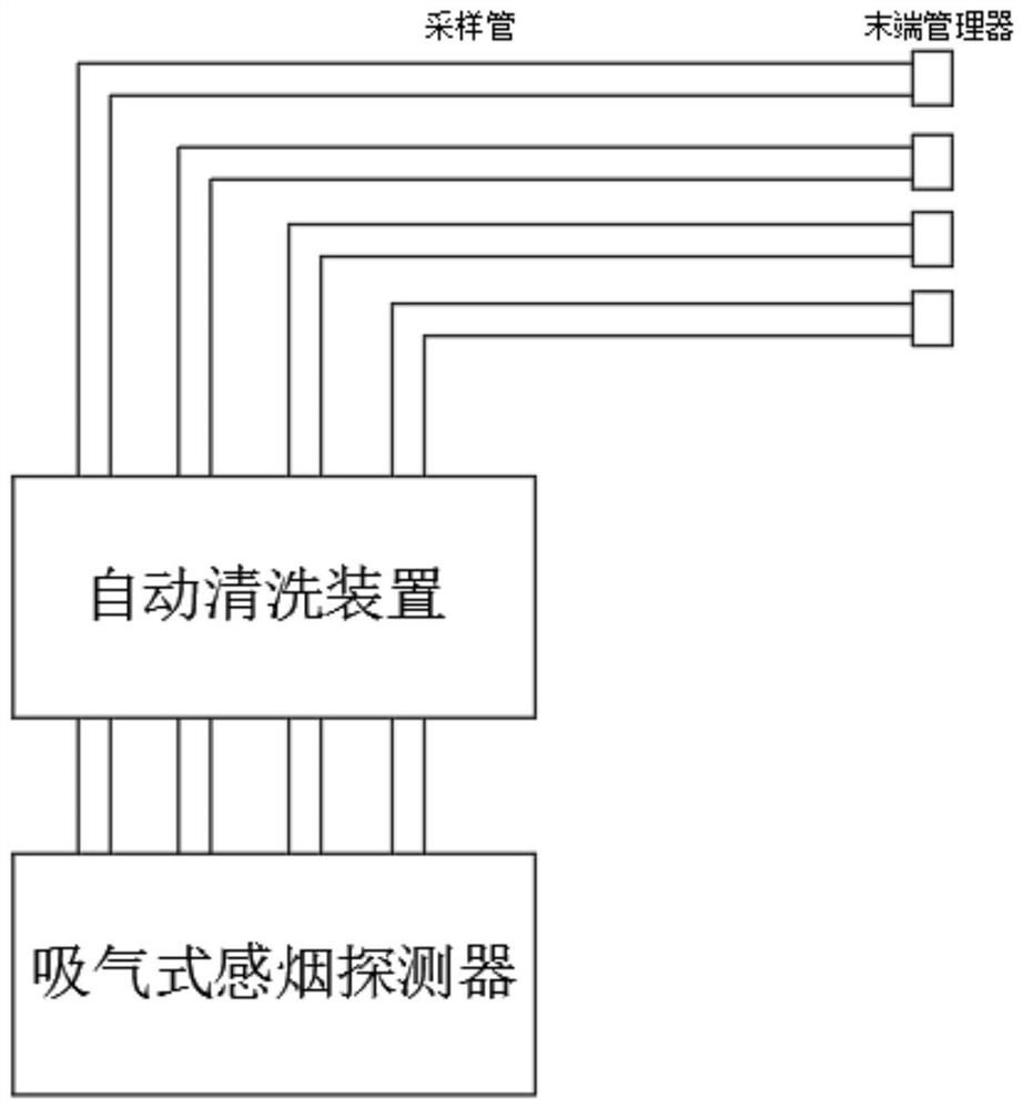
The invention discloses an automatic pipeline purging system and method, and relates to the technical field of pipeline cleaning. The automatic pipeline purging system comprises a high-pressure airflow generating device for generating high-pressure airflow; a channel switching module used for selecting sampling pipes and controlling the circulation direction of the high-pressure airflow; a backflow module used for carrying out backflow on the circulating high-pressure airflow; an airflow circulation module used for recycling the recycled airflow; and a control circuit used for controlling the high-pressure airflow generating device and the channel switching module. The automatic pipeline purging method comprises the steps that when the situation that the airflow is blocked is detected, the control circuit drives an electromagnetic valve to close airflow of three channels, and sampling pipe channels blocked by the airflow are reserved; a high-pressure fan is started to introduce the high-pressure airflow into a sampling pipe channel with a blocking fault, and foreign matters on a sampling hole are reversely blown away through the high-pressure air; and after a first channel is finished, whether the airflow fault is eliminated or not is detected again, and if the airflow fault is not eliminated, an alarm is given.

Description

technical field [0001] The disclosure of the present invention relates to the field of mechanical technology, in particular to an automatic flushing system and method for pipelines. Background technique [0002] The sampling pipe of the aspirating smoke detection device generally adopts PVC pipe, and the sampling hole on the sampling pipe is generally 2-3mm. These small holes are easily blocked by foreign matter such as dust, water droplets, fibers, insects, etc. The device cannot collect the air in the protected area, resulting in its function failure, especially in places with relatively large dust, this phenomenon occurs more frequently. [0003] In order to solve the problem of blockage of the sampling hole, the pipeline is generally cleaned manually, especially when the aspirating smoke detection device is installed in the high altitude, in the interlayer, on the upper part of the ceiling, etc., the frequent cleaning of the pipeline will bring greater damage Therefore,...

Claims


Application Information

Patent Timeline
IPC IPC(8): B08B9/032B08B13/00
CPCB08B9/0321B08B13/00
Inventor 李淮海李萌萌翁铢炜甘业清马雪婷严爽刘秋佳石进
Owner SHENZHEN CHA ZHI TECH
Learn More