
Automatic grabbing device for axle housing waste

A technology of grabbing device and horizontal moving device, which is applied in the direction of metal processing, etc., can solve the problems of circular waste clamping, inconvenience of manual picking up waste, and inability to adapt to clamping waste equipment, so as to improve production efficiency and reduce dangerous accidents Effect

Inactive Publication Date: 2021-05-28
XIAMEN AEROSPACE SIERT ROBOT SYST CO LTD
View PDF5 Cites 0 Cited by
  • Summary
  • Abstract
  • Description
  • Claims
  • Application Information

AI Technical Summary

Problems solved by technology

[0003] The purpose of the present invention is to provide an automatic grabbing device for axle housing waste, which solves the problems that it is inconvenient to pick up waste manually and that the equipment for clamping waste cannot adapt to the clamping of waste in different sizes.

Method used


Image

  • Automatic grabbing device for axle housing waste
  • Automatic grabbing device for axle housing waste
  • Automatic grabbing device for axle housing waste

Examples


Embodiment 1

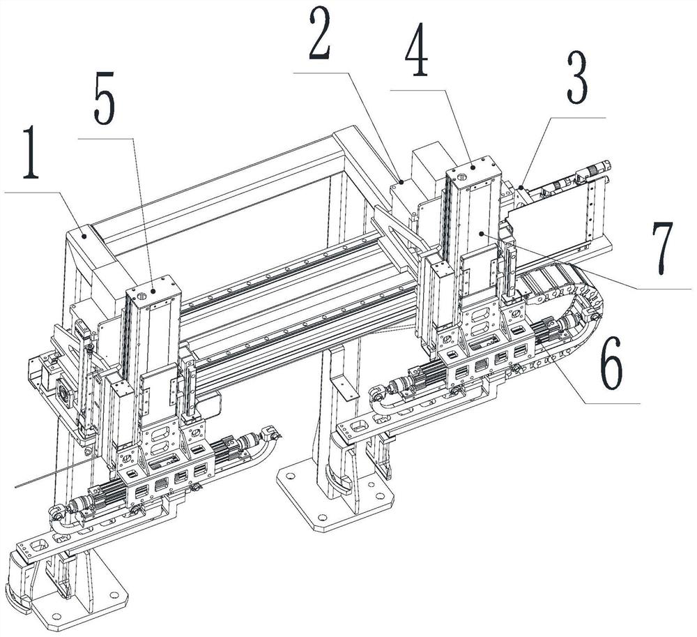
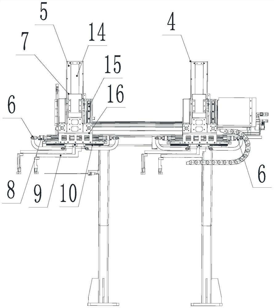
[0023] like figure 1 As shown, an automatic grabbing device for axle housing waste includes a support frame 1, and a blanking mechanism 2 is arranged on the support frame 1. The blanking mechanism 2 includes a horizontal moving device 3 connected to the supporting frame 1, and the horizontal moving device 3 is provided with a first clamping device 4 and a second clamping device 5, the first clamping device 4 and the second clamping device 5 are slidingly connected with the horizontal moving device 3, the first clamping device 4 and the second clamping device 5 Fixture device 5 all comprises pneumatic gripper 6 and lifting device 7 that lifting pneumatic gripper 6 is useful; figure 2 As shown, the pneumatic gripper 6 includes a double-rod double-acting cylinder 8, and the piston rods at both ends of the double-rod double-acting cylinder 8 are hinged with grippers 9 that cooperate with each other. 9. The first guide rail 10 for sliding, the first guide rail 10 is connected to ...

Embodiment 2

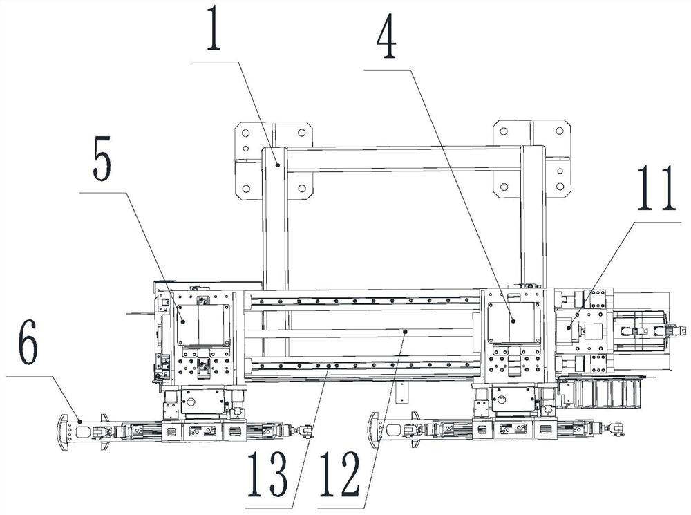
[0026] This embodiment is carried out on the basis of embodiment 1, as image 3 As shown, the horizontal moving device 3 includes a motor 11 for driving the first clamp device 4 and the second clamp device 5 to move, the motor 11 is connected to the support frame 1, and the support frame 1 is provided with a motor 11 for the first clamp device 4. With the second guide rail 13 that the second fixture device 5 slides, the second guide rail 13 is horizontally arranged on the support frame 1, and the lead screw 12 that is parallel to the second guide rail 13 is also provided on the support frame 1, and the lead screw 12 It is connected with the motor 11 through a shaft coupling, and a nut seat is connected under the first fixture device 4 and the second fixture device 5, and the two nut seats are all sleeved on the leading screw 12, and the two nut seats are both Screwed with the lead screw 12, the second guide rail 13 provided provides the motor 11 to drive the lead screw 12 to r...

Embodiment 3

[0028] This embodiment is carried out on the basis of Embodiment 1, such as Figure 5 As shown, the blanking mechanism 2 also includes an iron filing frame 17 for collecting iron filings. The iron filing frame 17 is located below the first fixture device 4, and the waste chips generated during the cutting process fall to the blanking mechanism 2. Arrive iron filings material frame 17 automatically.


PUM


Abstract

The invention discloses an automatic grabbing device for axle housing waste, belongs to the technical field of automobile axle housing clamps, and solves the problems that manual waste picking is inconvenient and waste clamping equipment cannot adapt to clamping of round cutting waste of different sizes. The automatic grabbing device for the axle housing waste comprises a supporting frame, wherein a discharging mechanism is arranged on the supporting frame, the discharging mechanism comprises a horizontal moving device, a first clamp device and a second clamp device, the first clamp device and the second clamp device are arranged on the horizontal moving device, and each clamp device comprises a pneumatic gripper and a lifting device. The device can achieve full-automatic waste grabbing and can adapt to round cutting waste grabbing of various products, in the working process, the pneumatic grippers grab the cut round waste, the pneumatic grippers are lifted by the lifting devices to move up and down, the horizontal moving device horizontally pushes the pneumatic grippers to grab the cut round waste to move left and right in the horizontal direction, and the problem of manual carrying is solved through circulating work in the mode.

Description

technical field [0001] The invention belongs to the technical field of automobile axle housing fixtures, in particular to an automatic grabbing device for axle housing waste. Background technique [0002] The axle casing cutting station robot automatically loads the material, and the circle cutting robot cuts the cutting waste in the shape of a workpiece. For different axle casing products, the diameter of the cutting circle varies according to the product. The picking equipment used in the factory now Too much clamping is too single, the picking work of the clamping equipment can only clamp the workpiece of the same size, and some of the cutting wastes are manually picked up and cut. The long-term work requires the input of personnel and the required The cost is huge, and the residual temperature of the waste after cutting by the circular cutting robot is prone to burn hazards. There are certain safety hazards in the process of work. Even if the workers wear protective tool...

Claims


Application Information

Patent Timeline
Patent Type & Authority Applications(China)
IPC IPC(8): B23Q7/04
CPCB23Q7/043
Inventor 黄敏刘小波黄泽强宋忠杰
Owner XIAMEN AEROSPACE SIERT ROBOT SYST CO LTD
Learn More