Beam structure of a vacuum maglev pipeline and vacuum maglev pipeline

A magnetic levitation and vacuum technology, applied in the direction of roads, tracks, tunnel systems, etc., can solve the problems of complex construction and high height, and achieve the effects of convenient construction, reduced structure height and reasonable force

Active Publication Date: 2022-05-20
CHINA RAILWAY ENG CONSULTING GRP CO LTD +1
View PDF6 Cites 0 Cited by
  • Summary
  • Abstract
  • Description
  • Claims
  • Application Information

AI Technical Summary

Problems solved by technology

[0003] At present, the ultra-high-speed magnetic levitation technology for low-vacuum pipelines at home and abroad is in the initial test stage. The vacuum pipelines of foreign experimental nature are all steel pipe structures, which are high in height and complicated in construction.

Method used


Image

  • Beam structure of a vacuum maglev pipeline and vacuum maglev pipeline
  • Beam structure of a vacuum maglev pipeline and vacuum maglev pipeline

Examples


Embodiment 1

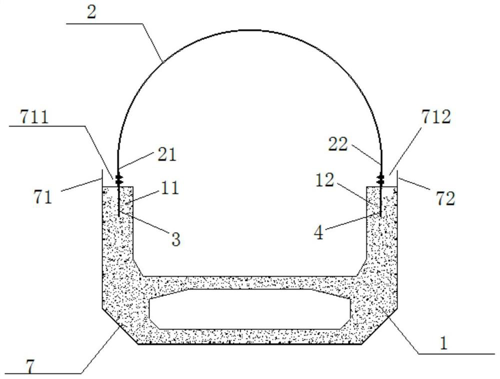
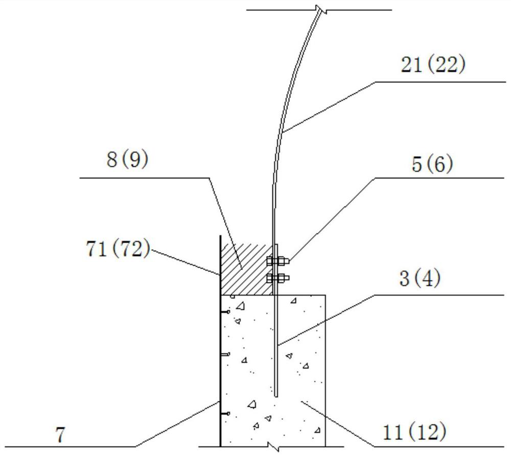
[0022] Figure 1-2The beam structure of the vacuum magnetic levitation pipe of the present invention is shown, which comprises: u-shaped bottom beam 1, which has a first beam end 11 and a second beam end 12, in the present embodiment, the U-shaped bottom beam 1 is a prestressed concrete structure in its entirety; And the first end portion 21 detachable connection, the second connection plate 4 is embedded within the second beam end 12, and the second end portion 22 detachable connection.

[0023] Specifically, the first connection plate 3 end is embedded within the first girder end 11, the other end is connected to the first end 21 by means of a first high-strength bolt 5 and the first end 21 removable; and / or, similarly, the second connection plate 4 is embedded at one end within the second beam end 12, the other end of the second end portion 22 through the second high-strength bolt 6 and the second end portion 22 detachable connection. Preferably, the first high-strength bolt ...

Embodiment 2

[0030] The present embodiment further provides a vacuum magnetic levitation pipe comprising a beam structure described in Examples I or II.


PUM


Abstract

The invention discloses a beam structure of a vacuum magnetic levitation pipeline and a vacuum magnetic levitation pipeline, comprising: a U-shaped bottom beam, which has a first beam end and a second beam end; an arc-shaped plate, which has a first end and a second beam end. two ends; and a first connecting plate and a second connecting plate, the first connecting plate is pre-embedded in the first beam end and is detachably connected to the first end, the second connecting plate is pre-buried Buried in the second beam end and detachably connected to the second end. The structure is simple and the construction is convenient. The U-shaped bottom beam that has been erected can become the channel for the subsequent beam transportation and erection, which can avoid the separate installation of pipelines on the load-bearing beam under the premise of ensuring a closed environment, which can effectively reduce the structure height and save manufacturing costs.

Description

Technical field [0001] The present invention relates to the field of vacuum magnetic levitation, in particular to a kind of vacuum magnetic levitation pipe beam structure and vacuum magnetic levitation pipeline. Background [0002] Ultra-high-speed maglev traffic generally refers to a new type of maglev system with a speed of more than 500km / h, which is mainly suitable for transportation scenarios with long transportation distance, large station spacing, multiple direct passenger flows, and wheel-rail high-speed rail is difficult to meet the requirements of time targets, mainly for passenger transportation between international and important urban agglomerations. The maglev traffic is laid in a closed vacuum pipe, which can effectively reduce the air resistance and noise of the train during ultra-high-speed operation, that is, the ultra-high-speed magnetic levitation technology of low-vacuum pipeline. [0003] At present, the ultra-high-speed magnetic levitation technology of low...

Claims


Application Information

Patent Timeline
Patent Type & Authority Patents(China)
IPC IPC(8): B61B13/10B60L13/04E01B25/30
CPCB61B13/10B60L13/04E01B25/30B60L2200/26Y02T30/00
Inventor 徐升桥李辉高策李少伟赵明贾允祥任晓博冯祁汪鹏翔
Owner CHINA RAILWAY ENG CONSULTING GRP CO LTD
Why Eureka
Try Eureka