Carton clamping device controlled by servo system

A technology of servo system and clamping device, which is applied in the field of servo system and can solve the problems of glue sticking to the surface of the carton and difficult to fall off.

Inactive Publication Date: 2021-05-28
陈健营
View PDF0 Cites 1 Cited by
  • Summary
  • Abstract
  • Description
  • Claims
  • Application Information

AI Technical Summary

Problems solved by technology

[0003] Because the label will not be torn off during the production of new cartons, but if the surface of the recycled carton is originally pasted with a large area of ​​label, it needs to be torn off, and the surface of the carton is oily, so the stickiness is relatively high. After the strong label is torn off, it is easy to produce glue that adheres to the surface of the carton, which leads to the clamping plate of the servo system controlling the carton clamping frame. When clamping this kind of carton, it is easy to make the side of the carton with glue stick directly When it is attached to the inside of the holding plate and it is difficult to come off

Method used


Image

  • Carton clamping device controlled by servo system
  • Carton clamping device controlled by servo system
  • Carton clamping device controlled by servo system

Examples


Embodiment 1

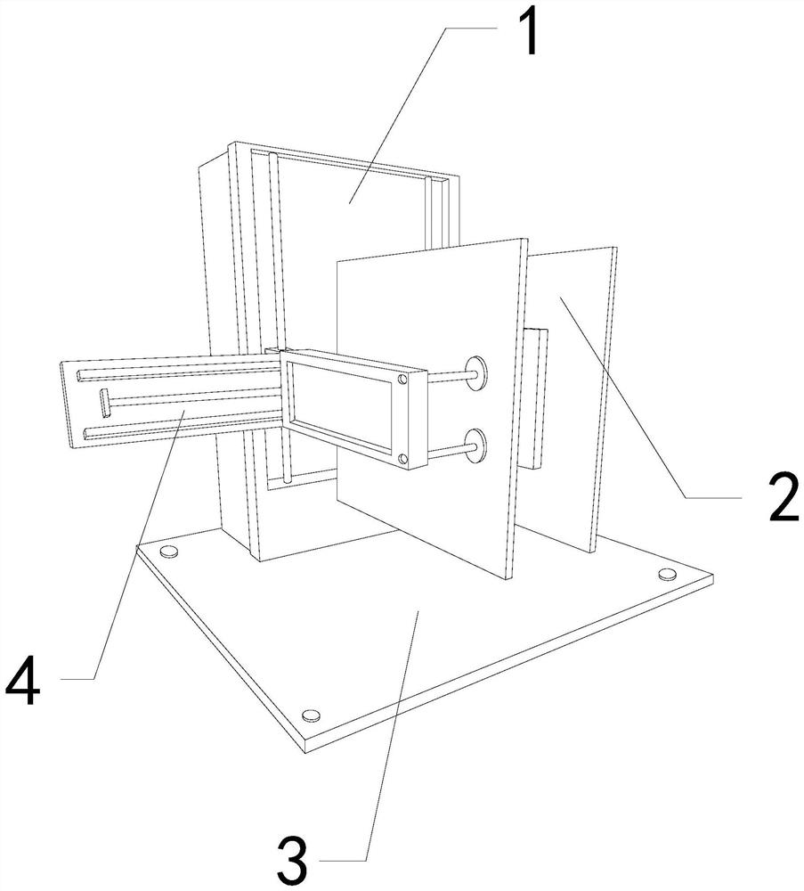
[0026] For example figure 1 -example Figure 5 Shown:

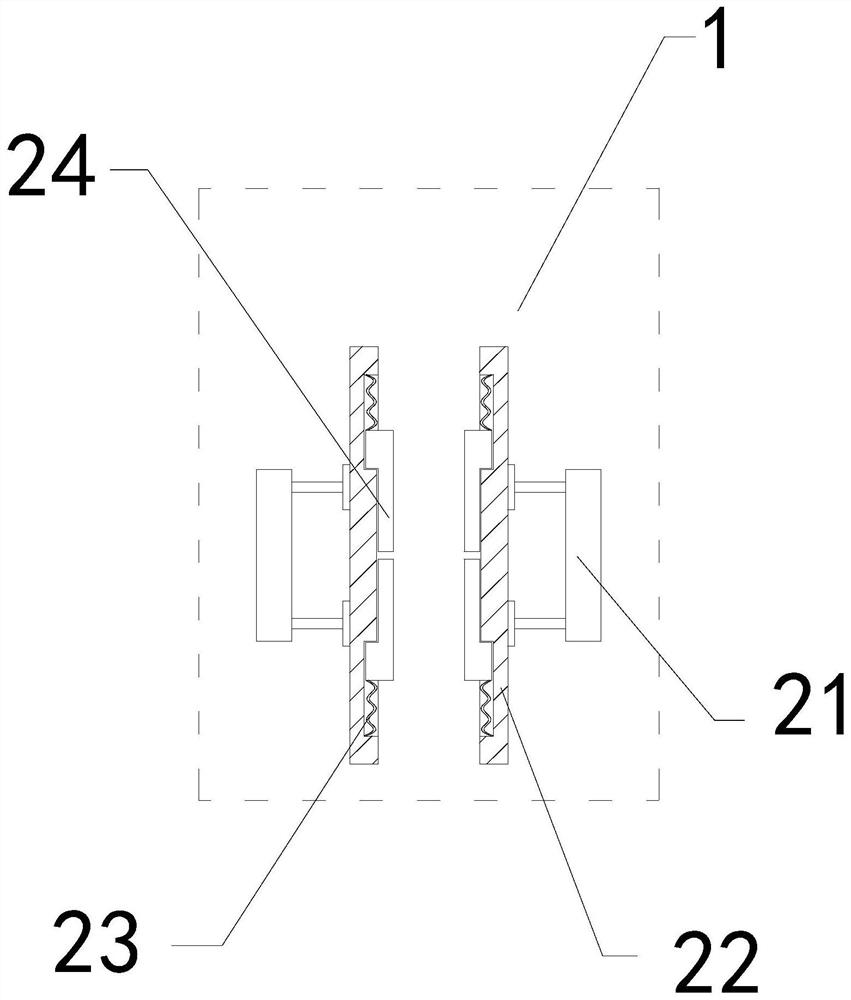
[0027] The present invention provides a servo system control carton clamping device, the structure of which includes a support panel 1, a clamping plate 2, a base 3, and a guide rail 4, the support panel 1 is embedded in the upper end of the base 3, and the guide rail 4 is connected to the support The front end of the panel 1 is connected, and the clamping plate 2 is movably engaged with the front end of the guide rail 4; The push frame 21 is fixed on the outer side of the contact plate 22 , the elastic bar 23 is installed between the force plate 24 and the inner wall of the contact plate 22 , and the force plate 24 is movably engaged with the inner side of the contact plate 22 .

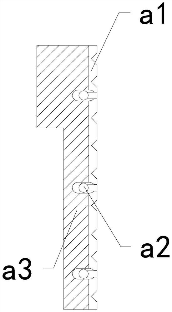
[0028] Wherein, the force bearing plate 24 includes a contact reducing surface a1, an extrapolation block a2, and a plate a3, the contact reducing surface a1 is embedded and fixed on the right side of the plate a3, and the extrapolating block...

Embodiment 2

[0034] For example Figure 6 -example Figure 8 Shown:

[0035] Wherein, the connecting frame a22 includes a contact plate c1, a linkage rod c2, a bearing plate c3, and a reverse thrust piece c4. The contact plate c1 is embedded and fixed on the right side of the linkage rod c2. The reverse push piece c4 is installed between the contact plate c1 and the bearing plate c3, and the thrust generated by the carton on the contact plate c1 can make the contact plate c1 move along the direction of the bearing plate c3 under the cooperation of the linkage rod c2. The inner contraction, and the contact plate c1 that has lost extrusion can be quickly pushed outward by the anti-thrust piece c4.

[0036]Wherein, the contact plate c1 includes a sliding rod c11, an outer contact plate c12, an extruding block c13, and a plate body c14. The outer contact plate c12 is embedded in the right side of the sliding bar c11. The plate body c14 is an integrated structure, the sliding rod c11 is enga...


PUM


Abstract

The invention discloses a carton clamping device controlled by a servo system.The carton clamping device structurally comprises a supporting panel, clamping plates, a base and a guide rail, wherein the supporting panel is fixedly embedded in the upper end position of the base; the guide rail is connected to the front end of the supporting panel; and the clamping plates are movably engaged with the front end of the guide rail. Through the extrusion of the inner walls of plate blocks on force-receiving frames, the force-receiving frames can slide rightwards along connecting frames under the cooperation of middle fixing rods, and then can be rapidly pushed to extend outwards through push-assisting pieces, so that outer push blocks can rapidly extend outwards so as to push a carton away from the outer surfaces of contact reduction surfaces. Therefore, the situation that the carton with glue on the outer surface is prone to be adhered to the surfaces of force-receiving plates and not easy to be detached is effectively avoided. Through the impact vibration on plate bodies generated by outer contact plates when the outer contact plates retract to the maximum extent, the outer push blocks can extend outwards along connecting fixing rods, so that the outer push blocks can extend outwards along the connecting fixing rods to push away the carton.

Description

technical field [0001] The invention relates to the field of servo systems, in particular to a servo system control carton clamping device. Background technique [0002] The servo system controls the carton clamping frame, which is mainly used for clamping and lifting the cartons. The clamping plates on both sides slide along the guide rails to the middle, so that the cartons can be clamped, and then the cartons can be driven up and down by the clamping plates. The guide rod is raised to transport the carton to a high place. Based on the above description, the inventors found that the existing servo system control carton clamping device mainly has the following deficiencies, for example: [0003] Because the label will not be torn off during the production of new cartons, but if the surface of the recycled carton is originally pasted with a large area of ​​label, it needs to be torn off, and the surface of the carton is oily, so the stickiness is relatively high. After the ...

Claims


Application Information

Patent Timeline
Patent Type & Authority Applications(China)
IPC IPC(8): B65G47/90B65G47/82
CPCB65G47/82B65G47/901B65G2201/0258
Inventor 陈健营
Owner 陈健营
Why Eureka
Try Eureka