
A data communication device and method in a CDMA communication system

A communication system and protocol data unit technology, applied in the field of logical transmission units, can solve problems such as reduction

Inactive Publication Date: 2003-11-19
SAMSUNG ELECTRONICS CO LTD
View PDF0 Cites 0 Cited by
  • Summary
  • Abstract
  • Description
  • Claims
  • Application Information

AI Technical Summary

Problems solved by technology

This means that the payload capacity for the MuxPDU is reduced by the size of the CRC field

Method used


Image

  • A data communication device and method in a CDMA communication system
  • A data communication device and method in a CDMA communication system
  • A data communication device and method in a CDMA communication system

Examples


Embodiment Construction

[0029] Preferred embodiments of the present invention will be described below with reference to the accompanying drawings. In the following description, well-known functions or constructions are not described in detail since they would obscure the invention in unnecessary detail.

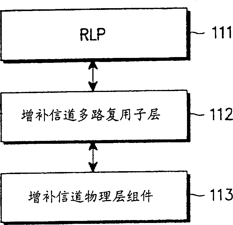
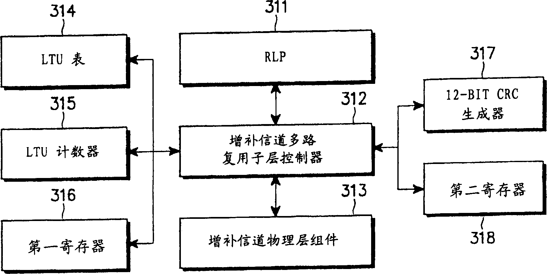
[0030] image 3 The multiplexing sublayer of assembling and disassembling LTUs in a CDMA communication system according to one embodiment of the present invention is shown. image 3 The structure of is applicable to both mobile stations and base stations.

[0031] refer to image 3 , the supplementary channel component 313 and the upper layer entity in this case the RLP 311 have the same figure 1 The same operation in . The remaining 6 components include multiplexing sublayers according to embodiments of the present invention. All functions of this embodiment of the invention are performed by the multiplexing sublayer controller 312 . image 3 Shows the newly added device. The LTU table 314 s...


PUM


Abstract

A method for arranging CRC (Cyclic Redundancy Code) bits within logical transmission units (LTUs) in a CDMA communication system having a physical channel frame comprised of a plurality of LTUs arranged in line, with a physical layer CRC field and tail bits arranged after the LTUs. Each LTU includes a payload and a LTU CRC field for detecting errors in the LTU payload. In the CRC bit arranging method, the CRC field included in odd-numbered LTUs are arranged after the payload and the CRC field included in even-numbered LTUs are arranged before the payload in such a manner that a LTU CRC field of an even-numbered LTU and a LTU CRC field of an odd-numbered LTU connected to said even-numbered LTU are sequentially arranged.

Description

technical field [0001] The present invention relates generally to CDMA communication systems, and more particularly to a method for assembling and de-assembling or disassembling Logical Transmission Units (LTUs) for efficient data transmission in a radio environment Apparatus and methods. Background technique [0002] Typically, CDMA-2000 systems have supplemental channels that operate at high data rates. figure 1 Shows the protocol layer structure of the supplementary channel in the CDMA-2000 system. Although a CDMA-2000 system has several different types of upper layer entities, but figure 1 The RLP (Radio Link Protocol) layer 111 of the upper entity is shown by way of example only. The RLP layer 111 assembles data received from an upper layer into an RLP frame. The multiplexing sublayer 112 receives RLP frames from the RLP layer and assembles the RLP frames into MuxPDUs (Multiplexing Sublayer Protocol Data Units). The supplemental channel physical layer component 113...

Claims


Application Information

Patent Timeline
Patent Type & Authority Patents(China)
IPC IPC(8): H04B1/69H04L1/00
CPCH04L1/0041H04L1/0061H04L1/0078H04J13/10
Inventor 张勋姜熙原朴沼坟
Owner SAMSUNG ELECTRONICS CO LTD
Learn More