
a sewing machine

A technology of interlock sewing machine and cloth feeding dog, which is applied in the direction of sewing machine components, sewing equipment, cloth feeding mechanism, etc. It can solve the problems of unfavorable cloth, affecting the sewing of thick materials, and placing it under the presser foot, so as to improve the feeding efficiency and Feed capacity, effect of high sewing demand

Active Publication Date: 2022-07-05
JACK SEWING MASCH CO LTD
View PDF14 Cites 0 Cited by
  • Summary
  • Abstract
  • Description
  • Claims
  • Application Information

AI Technical Summary

Problems solved by technology

[0004] 1. Before sewing, when the interlock sewing machine lifts the presser foot and puts in the fabric, the needle is at the highest point within its stroke range, and the needle, feed dog, and differential tooth are in a linkage relationship, all of which are driven by the main shaft Yes, at this time, the feed dog and the differential dog are also located at the highest points within their respective travel ranges, that is, the feed dog and the differential dog both protrude upward from the tooth grooves of the needle plate and are located above the needle plate, which is not conducive to Putting the fabric under the presser foot, especially the thick material, will affect the sewing of the heavy material
[0005] 2. The lifting height of the existing interlock sewing machine is a fixed value set at the factory, and the fixed lifting height can no longer meet the adaptability of different fabrics. For different fabrics and fabric thicknesses, the fixed lifting height is reduced Improve the cloth feeding efficiency and cloth feeding ability of interlock sewing machine

Method used


Image

  • a sewing machine
  • a sewing machine
  • a sewing machine

Examples


Embodiment Construction

[0056] The embodiments of the present invention are described below by specific embodiments, and those skilled in the art can easily understand other advantages and effects of the present invention from the contents disclosed in this specification.

[0057] It should be noted that the structures, proportions, sizes, etc. drawn in the accompanying drawings in this specification are only used to cooperate with the contents disclosed in the specification for the understanding and reading of those who are familiar with the technology, and are not intended to limit the conditions for the implementation of the present invention. Therefore, it does not have technical substantive significance, and any structural modification, proportional relationship change or size adjustment should still fall within the scope of the present invention without affecting the effect that the present invention can produce and the purpose that can be achieved. within the scope of technical content. At the...


PUM


Abstract

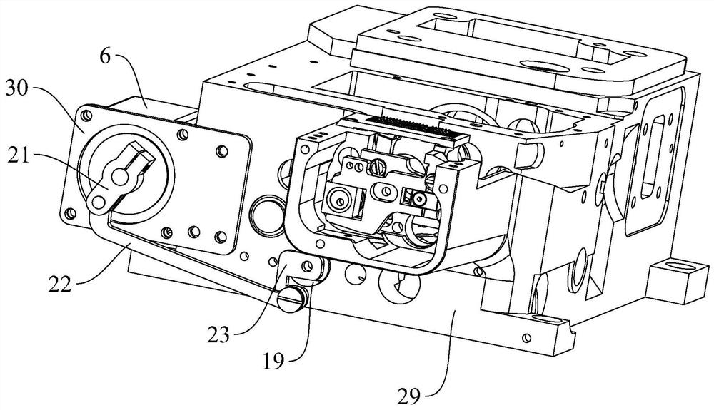
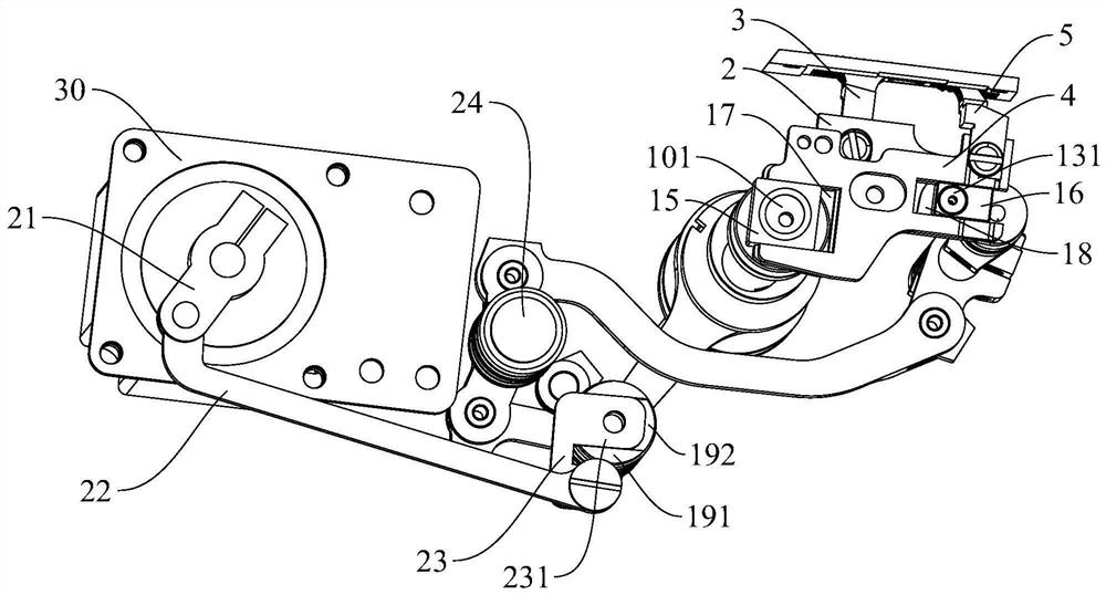
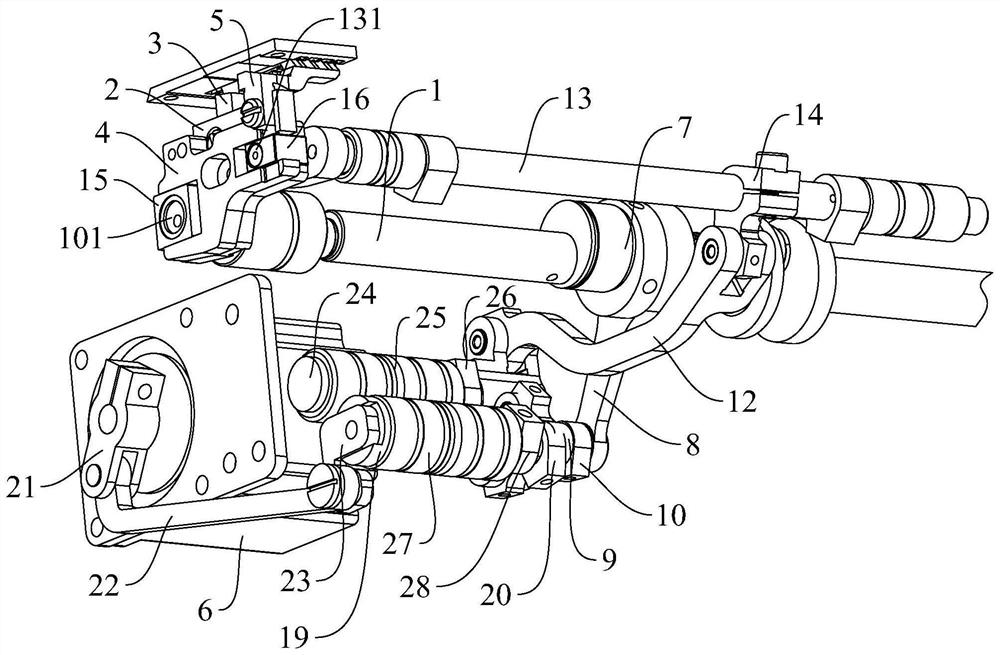
The invention provides an interlock sewing machine, comprising a main shaft, a cloth feed dog frame, a cloth feed dog installed on the cloth feed dog frame, a differential tooth frame, a differential tooth installed on the differential tooth frame, a tooth lifting mechanism, The driving source and the transmission assembly, the main shaft is connected with the feeding tooth frame and the differential tooth frame through the tooth lifting mechanism, and the driving source is connected with a tooth lifting transmission part in the tooth lifting mechanism through the transmission assembly; when the driving source moves, it passes through the transmission assembly. Acting on the tooth-lifting transmission part, changing the inclination of the tooth-lifting transmission part, or driving the feed dog and the differential tooth to descend. The present application can realize the automatic lowering of the feed dog and the differential dog when the cloth is placed, so that the cloth can be placed under the presser foot, and then the drive source can be reset to reset the entire set of the tooth-lifting mechanism of the interlock sewing machine; After the source moves and remains in the position after the action, change the inclination of a tooth-lifting transmission part in the tooth-lifting mechanism, thereby changing the transmission efficiency of the tooth-lifting mechanism, realizing the adjustable height of the tooth-lifting, and improving the cloth feeding of the interlock sewing machine. Efficiency and feed capacity.

Description

technical field [0001] The present invention relates to an interlock sewing machine. Background technique [0002] At present, the interlock sewing machine is equipped with a main shaft, a cloth feed dog frame and a differential dog frame arranged side by side along the axis of the main shaft, a cloth feed dog installed on the cloth feed dog frame, and a differential dog frame installed on the differential dog frame. The moving teeth, the cloth feeding mechanism, and the teeth lifting mechanism, such as an interlock sewing machine disclosed in the Chinese invention patent with the application number of 201510219424.1. Among them, the main shaft is connected with the cloth feed dog frame and the differential dog frame through the cloth feeding mechanism, and drives the back and forth movement of the cloth feed dog frame and the differential dog frame in the horizontal direction, and the movement in this direction controls the stitch length of the interlock sewing machine. si...

Claims


Application Information

Patent Timeline
Patent Type & Authority Patents(China)
IPC IPC(8): D05B27/24
CPCD05B27/24
Inventor 李卫超王志金海啸田国兵杨聪聪
Owner JACK SEWING MASCH CO LTD
Learn More