
Novel energy-saving self-balancing vertical lifting type movable bridge

A self-balancing, straight-up technology, applied in the direction of open bridges, vertical bridges, bridges, etc., can solve problems such as high engineering costs, large amount of materials, and difficult layout of lifting towers, so as to ensure safety and economy, and reduce energy consumption. consumption effect

Pending Publication Date: 2021-05-28
CCCC FHDI ENG
View PDF0 Cites 2 Cited by
  • Summary
  • Abstract
  • Description
  • Claims
  • Application Information

AI Technical Summary

Problems solved by technology

If the opening span is increased to 100m, according to the above bridge deck width and reference to the relevant weight indicators, it is estimated that the lifting weight of the opening span of 100m span will reach about: 730×(100 / 53.6)×1.5 (considering the bridge span increase The amount of opening span structure material consumption increase that causes)=2043 tons, as also according to the balance counterweight of configuration 97%, then the weight of balance counterweight is 2043*97%=1981.7 tons, and counterweight also adopts steel (iron), then The volume of the counterweight is 1981.7 / 7.85=252.5 cubic meters, and the volumes distributed in the four towers are 63.1 cubic meters respectively. Therefore, with the increase of the opening span, the counterweight configured not only requires a large amount of materials and high engineering costs, but also Moreover, due to the large increase in volume, it is difficult to arrange in the lifting tower

Method used


Image

  • Novel energy-saving self-balancing vertical lifting type movable bridge
  • Novel energy-saving self-balancing vertical lifting type movable bridge
  • Novel energy-saving self-balancing vertical lifting type movable bridge

Examples


Embodiment Construction

[0020] The present invention will be further described below in conjunction with accompanying drawing by specific embodiment:

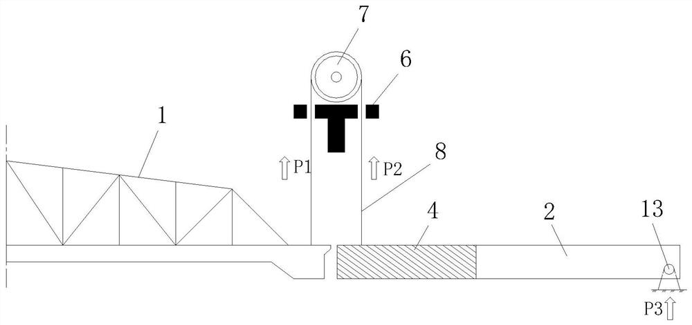
[0021] In this example, refer to Figure 1-Figure 3 , the new energy-saving self-balancing direct-lift opening bridge includes an opening span 1, a lifting tower 5, a load-bearing sling 8 and a driving drum 7, the opening span 1 is located between the lifting towers 5, and the driving drum 7 is installed on the lifting In the tower 1, the load-bearing sling 8 is wound around the driving drum 7, and the opening span 1 is connected to the load-bearing sling 8; each self-balancing side span 2 is provided on the outside of the lifting tower 5, and the load-bearing sling 8 bypasses the driving drum. The cylinder 7 is connected to the end of the self-balancing side span 2 close to the lifting tower 5, so that this end of the self-balancing side span 2 forms a vertical movable end, and the other end of the self-balancing side span 2 is hingedly connected to ...


PUM


Abstract

A disclosed novel energy-saving self-balancing vertical lifting type movable bridge comprises an opening span, a lifting tower, a bearing sling and a driving rotary drum, self-balancing side spans are arranged in the outer sides of the lifting tower respectively, the bearing sling bypasses the driving rotary drum and then is connected with the ends, close to the lifting tower, of the self-balancing side spans, and the ends of the self-balancing side spans form vertical movable ends; and the other end of each self-balancing side span is hinged with the fixed part to form a connecting structure capable of rotating up and down, so that the vertical movable end of the self-balancing side span is adjacent to the opening span. By means of the structural self-weight of the rotatable self-balancing side spans and the additional balance weight arranged in the self-balancing side spans, the vertical gravity of the self-balancing side spans at one side of the lifting tower is approximately equal to the vertical gravity of one end of the opening span, so that the balance weight arranged in the lifting tower is completely omitted, the applicable span of the vertical lifting type movable bridge is expanded, and the energy consumption of opening and closing operation can be reduced.

Description

technical field [0001] The invention relates to the technical field of bridge construction engineering, in particular to a direct lift open bridge. Background technique [0002] In bridge engineering, in some special cases, it is very suitable to use a bridge that can be opened - an open bridge. The open span adopts the direct lifting opening method. Due to the simple force and convenient operation, it is a commonly used opening method for the open bridge. The lifting can be achieved by setting the balance weight, which greatly reduces the power requirements and energy consumption. For example, the opening bridge of Panyu Guangming Bridge in Guangzhou City adopts a direct lift opening bridge with counterweight. When it is necessary to allow large ships to pass, the opening span of the bridge needs to be lifted vertically to a certain height to meet the clearance requirements of large ships. When ships are blocked and land traffic connection is required, the bridge needs to...

Claims


Application Information

Patent Timeline
IPC IPC(8): E01D15/02E01D15/06E01D12/00E01D101/24E01D101/30
CPCE01D12/00E01D15/02E01D15/06E01D2101/24E01D2101/30
Inventor 杨云安许晔
Owner CCCC FHDI ENG
Learn More