Silt removing head steering device

A technology of steering device and silt head, which is applied in the direction of earth mover/shovel, mechanically driven excavator/dredger, construction, etc. It can solve the problems of waste of water resources, time-consuming and labor-intensive dredging methods, and low efficiency. , to achieve the effect of timely steering and simple and reliable steering method

Inactive Publication Date: 2021-05-28
衡阳市稼乐农机科技有限公司
View PDF0 Cites 0 Cited by
  • Summary
  • Abstract
  • Description
  • Claims
  • Application Information

AI Technical Summary

Problems solved by technology

[0003] 1. Ordinary mud pumps that have been on the market since the 1980s can only pump thinner mud or sewage. For those that have settled for a long time and the mud is hard, it is necessary to drain all the water first, and then rinse with a high-pressure water gun. After the mud is thinned, it is sucked away by the mud pump. This dredging method is labor-intensive and time-consuming, and the efficiency is extremely low. More importantly, it also wastes water resources.
[0004] 2. Use a bucket truck to pull the mud out of the pond with a mixer. The mud pulled out is very thick, but the working method is very troublesome and the efficiency is very low. At the same time, it is limited by the conditions and environment.

Method used


Image

  • Silt removing head steering device
  • Silt removing head steering device
  • Silt removing head steering device

Examples


Embodiment 1

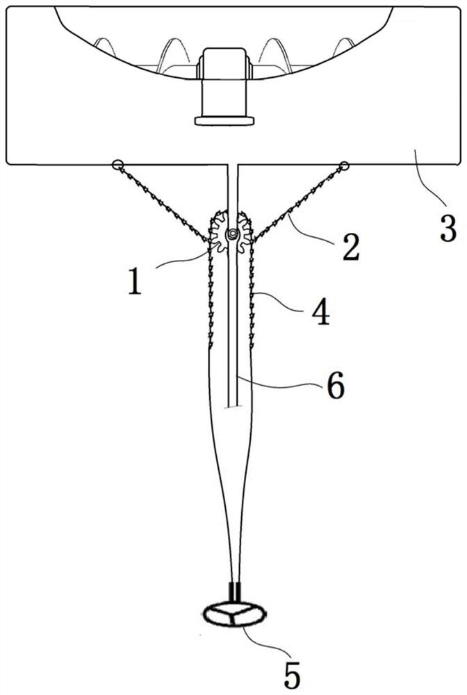
[0029] Example 1 ( figure 1 No number 7, 8 in

[0030] A dredging head steering device, such as figure 1 As shown, the steering rod 8 comprising the steering gear 1 and the steering wheel 5 installed on the floating support device is wound around the first steering chain 2 mounted on the steering gear 1, and one end of the first steering chain 2 is connected to the dredging by a rope. The left end of head 3 is connected, and the other end of this first turning chain 2 is connected with the right end of dredging head 3 by rope. In other words, the two ends of the first steering chain 2 are respectively connected with the dredging head 3 through ropes. The second steering chain 4 is also wound around the steering gear 1, and one end of the second steering chain 4 is connected with the steering rod 8 of the steering wheel 5 installed on the floating support device through a rope. The other end is connected with the steering rod 8 of the steering wheel 5 installed on the floati...

Embodiment 2

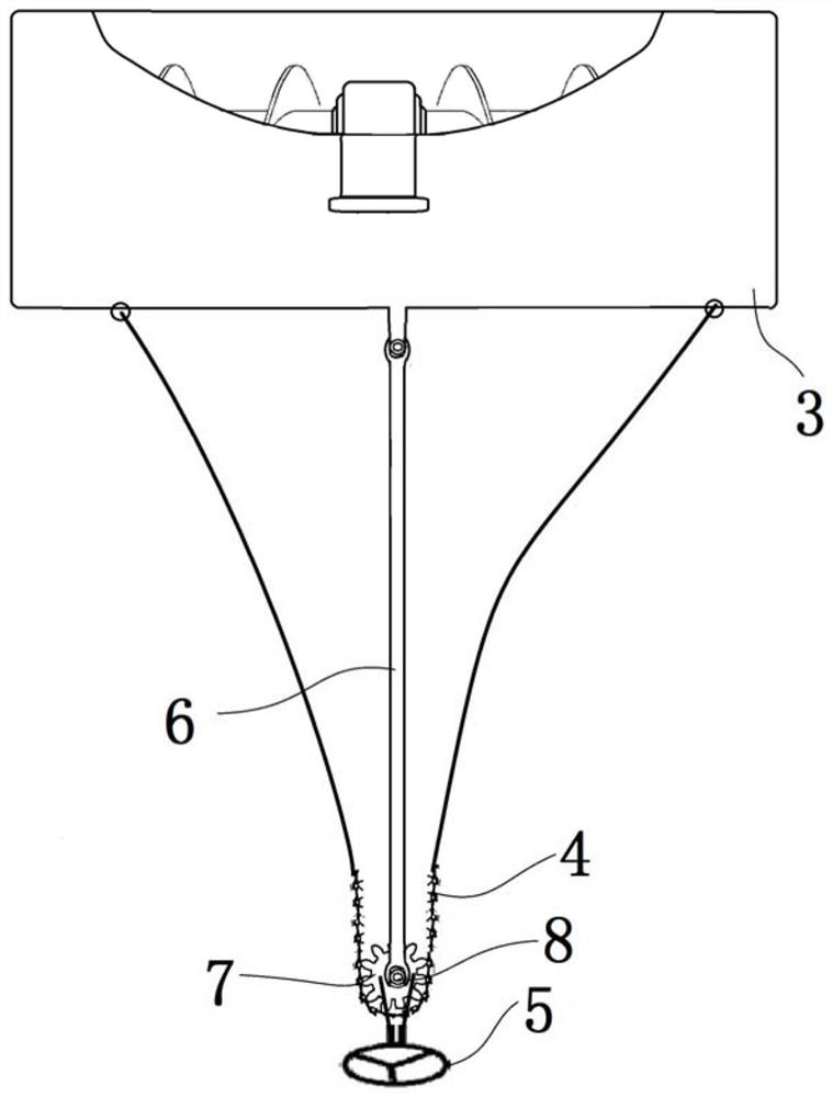
[0033] A dredging head steering device, such as figure 2 As shown, it includes a steering rod 8 mounted on a floating support device and a steering wheel 5 mounted on the top of the steering rod 8; a steering gear 7 is installed on the steering rod 8, and a steering chain is wound on the steering gear 7; One end of the chain is connected with the left end of the dredging head 3 by a rope, and the other end of the steering chain is connected with the right end of the dredging head 3 by a rope. In other words, the two ends of the steering chain are respectively connected to the dredging head 3 by ropes.

[0034] Thus, when a turn is needed, the operator drives the steering gear 7 to rotate by the steering of the steering wheel 5, and the steering gear 7 drives the steering chain to move, and the steering chain then directly drives the dredging head 3 to turn left or turn right.

[0035] Preferably, the floating support device includes at least two buoys and a support frame, an...

Embodiment 3

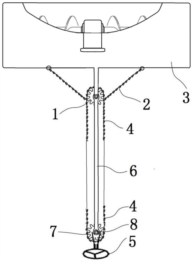
[0037] Similar to the front-end part of Embodiment 1, such as image 3 As shown, the difference is that the steering rod 8 is equipped with a steering gear 7, and the second steering chain 4 is wound around the steering gear 7 and the steering gear 1. Thus, when turning is required, the operator turns the steering wheel 5 to drive the steering gear 1 to rotate through the second steering chain 4, thereby driving the first steering chain 2 mounted on the steering gear 1 to move relative to the steering gear 1, and finally Drive the dredging head 3 to turn left or turn right.


PUM


Abstract

The invention discloses a silt removing head steering device which comprises a steering gear and a first steering chain winding the steering gear. One end of the first steering chain is fixed to a left end part of the silt removing head while the other end of the first steering chain is fixed to a right end part of the silt removing head; a second steering chain winds the steering gear, one end of the second steering chain is connected with a steering wheel assembled on a floating supporting device and the other end of the second steering chain is connected with a steering rod of the steeling wheel assembled on floating supporting device. The silt removing head steering device steers timely and is easy to operate, convenient to use and low in cost.

Description

technical field [0001] The invention relates to a steering device for a dredging head, belonging to the field of dredging equipment. Background technique [0002] The current mainstream mechanical desilting methods are as follows: [0003] 1. Ordinary mud pumps that have been on the market since the 1980s can only pump thinner mud or sewage. For those that have settled for a long time and the mud is hard, it is necessary to drain all the water first, and then rinse with a high-pressure water gun. After the thin mud is formed, it is sucked away by the mud pump. This dredging method is labor-intensive and time-consuming, the efficiency is extremely low, and more importantly, it also wastes water resources. [0004] 2. Use a bucket truck to pull the mud out of the pond with a mixer. The mud pulled out is very thick, but the working method is very troublesome and the efficiency is very low. At the same time, it is limited by the conditions and environment. [0005] 3. Use an e...

Claims


Application Information

Patent Timeline
IPC IPC(8): E02F5/28E02F3/92
CPCE02F3/9243E02F5/282
Inventor 王志高
Owner 衡阳市稼乐农机科技有限公司
Why Eureka
Try Eureka