Single-beam three-degree-of-freedom homodyne laser interferometer based on array detector

A laser interferometer and array technology, applied in the field of laser applications, can solve the problems of limiting the three-degree-of-freedom measurement capability of the laser interferometer, the angle decoupling nonlinearity of the differential wavefront interferometer, and the multi-axis periodic nonlinear coupling, etc. The effect of improving the angle measurement range, the simple optical path, and the cost-effectiveness advantage

Active Publication Date: 2021-05-28
HARBIN INST OF TECH
View PDF18 Cites 4 Cited by
  • Summary
  • Abstract
  • Description
  • Claims
  • Application Information

AI Technical Summary

Problems solved by technology

The representative one is the compact differential wavefront interferometer (Yu X., Gillmer S.R., Ellis J.D. Beam Geometry, Alignment, and Wavefront Aberration Effects on Interferometric Differential Wavefront Sensing [J]. Measurement Science and Technology ,2015,26(12):125203), but the differential wavefront interferometer has the principle error of angle decoupling nonlinearity and directly limits the angle measurement accuracy and angle measurement range, resulting in its angle measurement range being larger than that of traditional heterodyne laser interferometry The instrument is smaller, usually in the order of 0.1mrad or below
[0007] In summary, the existing laser interferometer based on parallel beam measurement has the problems of complex structure, extremely difficult processing and multi-axis periodic nonlinear coupling. The differential wavefront interferometer for single-beam measurement has the problems of angular coupling nonlinearity and small angular measurement range, which seriously limits the improvement of the three-degree-of-freedom measurement capability of laser interferometers

Method used


Image

  • Single-beam three-degree-of-freedom homodyne laser interferometer based on array detector

Examples


Embodiment Construction

[0027] Specific embodiments of the laser interferometer proposed by the present invention will be described in detail below in conjunction with the accompanying drawings.

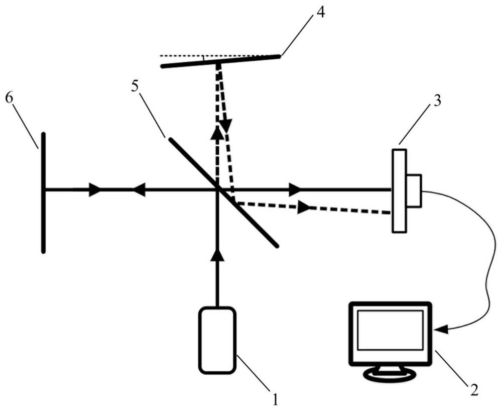
[0028] like figure 1The shown single-beam three-degree-of-freedom homodyne laser interferometer based on array detectors includes a laser light source 1, a host computer 2, an array detector 3, a fixed reference plane reflector 4, and a non-polarization beam-splitting film coated The first beam splitting surface 5, the movable target plane mirror 6; the laser light source 1 provides the first input beam; the fixed reference plane mirror 4, the first beam splitting surface 5 and the movable target plane mirror 6 form Michelson Interference structure; the host computer 2 and the array detector 3 form an array detection and signal decoupling module; the reflection surface of the fixed reference plane mirror 4 is not perpendicular to the first reference beam, so that the first measurement beam and the first ref...


PUM


Abstract

The invention discloses a single-beam three-degree-of-freedom homodyne laser interferometer based on an array detector, and belongs to the technical field of laser application. According to the invention, a single-frequency laser beam is input to the Michelson interference structure, the angle of the reference plane mirror is set to make the measurement beam and the reference beam perform non-coaxial interference and form a single-beam homodyne interference signal, and the array detector is selected to effectively receive the single-beam homodyne interference signal. Finally, three-degree-of-freedom signal linear decoupling on the single-beam homodyne interference signal is achieved through a three-degree-of-freedom decoupling method based on Lissajous ellipse fitting. The laser interferometer does not have angle decoupling nonlinearity, the period nonlinear error is remarkably reduced, compared with other existing three-degree-of-freedom laser interferometers, the laser interferometer has the advantages of being simple in structure, large in angle measurement range and easy to integrate, and the high-precision requirement of the three-degree-of-freedom laser interferometer for displacement and angle measurement is met.

Description

technical field [0001] The invention belongs to the technical field of laser applications, and mainly relates to a single-beam three-degree-of-freedom homodyne laser interferometer based on an array detector. Background technique [0002] Laser interferometry technology is the basic core technology in precision engineering, and plays a very important role in the fields of precision measurement, high-end equipment manufacturing and large scientific devices. With the rapid development of the above fields in recent years, not only the accuracy of displacement measurement needs to be improved from nanometer level to sub-nanometer or even picometer level, but also the form of displacement measurement needs to be changed from single-axis displacement measurement to multi-axis / angular displacement three-dimensional Composite measure of degrees of freedom. [0003] At present, the most widely used in the field of multi-axis laser interferometry is the laser interferometer based on ...

Claims


Application Information

Patent Timeline
Patent Type & Authority Applications(China)
IPC IPC(8): G01B9/02G01B11/26
CPCG01B9/02G01B11/26G01B9/02083G01B9/02027G01B9/02019G01B11/005
Inventor 于亮胡鹏程林雄磊苏晓博
Owner HARBIN INST OF TECH
Why Eureka
Try Eureka