Unit detector optical tomography time-division modulation imaging system

A unit detector, optical tomography technology, applied in the parts, electrical components, image communication and other directions of TV systems, can solve problems such as unsatisfactory resolution, achieve high resolution, reduce rotation eccentricity, reconstruct two 3D image clarity

Active Publication Date: 2022-04-08
HEFEI UNIV OF TECH
View PDF0 Cites 0 Cited by
  • Summary
  • Abstract
  • Description
  • Claims
  • Application Information

AI Technical Summary

Problems solved by technology

[0003] In order to solve the defect that the resolution of the imaging detection device in the prior art is very unsatisfactory in the natural light environment, the present invention proposes a unit detector optical tomography time-division modulation imaging system

Method used


Image

  • Unit detector optical tomography time-division modulation imaging system
  • Unit detector optical tomography time-division modulation imaging system
  • Unit detector optical tomography time-division modulation imaging system

Examples


Embodiment Construction

[0036] Name explanation: The incident window diameter is called the angle of the incident pupil center, referred to as the object side, referred to as the object side field; the number of shot window diameter to the center of the emitting pupil is called like a square angle, reflective Vocation;

[0037] MM: mm; cm: cm.

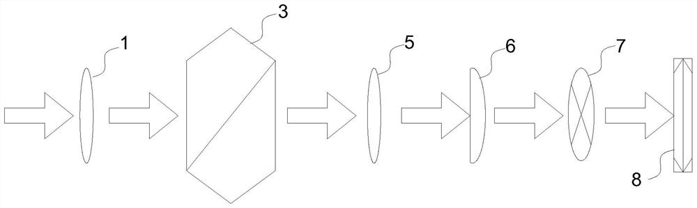
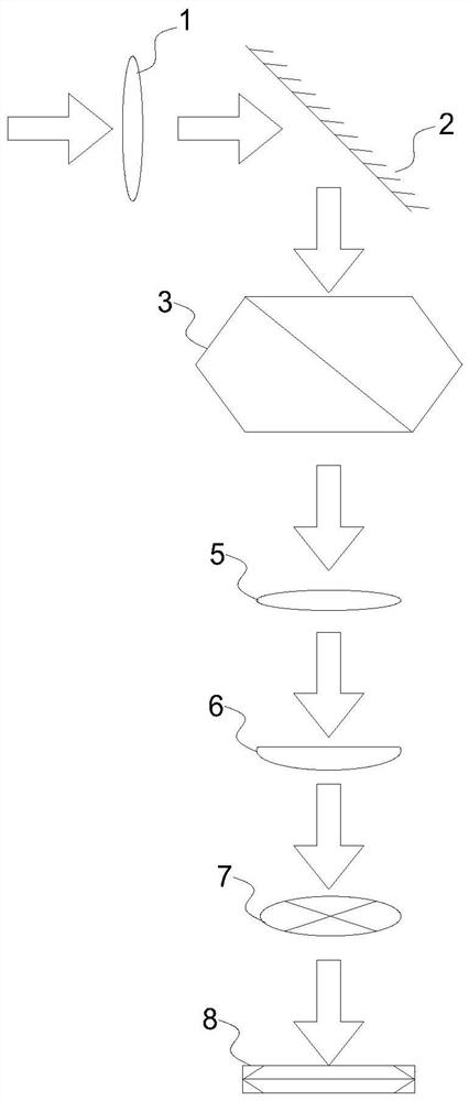
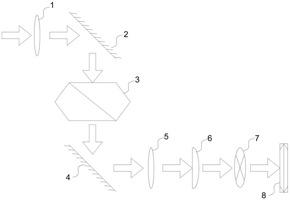
[0038] The present embodiment proposed a unit detector optical chromatographic scanning time division imaging system, including a like rotating device 3, a cylinder 6, and an imaging detector 8 arranged in the front direction sequential order of the imaging surface of the object to be formed. The object to be imaged, like a rotating device 3, the cylinder 6, and the imaging detector 8 are arranged in the direction of the light propagation direction, and in the optical propagation direction, the imaging surface to be imaged in the image is toward the image rotation device 3.

[0039] The rotating device 3 is used to rotate the incident image to generate a rotary i...


PUM


Abstract

A unit detector optical tomography time-division modulation imaging system, including an image rotation device, a cylindrical mirror and an imaging detector sequentially arranged along the front direction of the imaging surface of an object to be imaged; The image is rotated to generate a rotated image; the cylindrical mirror is used for one-dimensional integral amplification of the incident rotated image; the imaging detector is used for collecting the rotated image after the one-dimensional integral amplification of the cylindrical mirror. The invention implements one-dimensional integration of the optical signal through the cylindrical mirror to realize the signal enhancement of the optical signal, that is, the pixel value of the rotating image passing through the cylindrical mirror is increased in the integration direction. Through the cooperation of the cylindrical mirror and the imaging detector, it is equivalent to the second integration of the reflected light of the object to be imaged, making it easier to distinguish the pixels of the rotating image obtained by the imaging detector, so that the reconstruction of the finally obtained object to be imaged Two-dimensional images are much clearer.

Description

Technical field [0001] The present invention relates to the field of imaging, and more particularly to a unit detector optical chromatographic scanning time modulation imaging system. Background technique [0002] Target detection and tracking is a research topic that people have always been very interested. In order to pursue a better target detection, the detection of target imaging technology has been attacked. Existing imaging detecting devices, mostly used in parallel light environments, and the resolution in natural light environments is very unsatisfactory. Inventive content [0003] In order to solve the resolution of the imaging detecting device in the prior art in a natural light environment, the present invention proposes a unit detector optical chromatographic scanning time modulation imaging system. [0004] The object of the present invention adopts the following technical solutions: [0005] A unit detector optical tomography scanning time modulation imaging syste...

Claims


Application Information

Patent Timeline
Patent Type & Authority Patents(China)
IPC IPC(8): H04N5/225H04N5/217H04N5/232
CPCH04N23/81H04N23/54H04N23/50H04N23/55H04N23/80H04N23/695
Inventor 李保生韩宝坤
Owner HEFEI UNIV OF TECH
Why Eureka
Try Eureka