Unit detector optical tomography time division modulation imaging system

A unit detector, optical tomography technology, applied in the parts, electrical components, image communication and other directions of TV systems, can solve problems such as unsatisfactory resolution

Active Publication Date: 2021-05-28
HEFEI UNIV OF TECH
View PDF6 Cites 0 Cited by
  • Summary
  • Abstract
  • Description
  • Claims
  • Application Information

AI Technical Summary

Problems solved by technology

[0003] In order to solve the defect that the resolution of the imaging detection device in the prior art is very unsatisfactory in th

Method used


Image

  • Unit detector optical tomography time division modulation imaging system
  • Unit detector optical tomography time division modulation imaging system
  • Unit detector optical tomography time division modulation imaging system

Examples


Embodiment Construction

[0036] Explanation of the name: The opening angle of the diameter of the entrance window to the center of the entrance pupil is called the object-side field of view, referred to as the object-side field of view; the opening angle of the diameter of the exit window to the center of the exit pupil is called the image-side field of view, referred to as the image-side field of view field of view;

[0037] mm: millimeter; cm: centimeter.

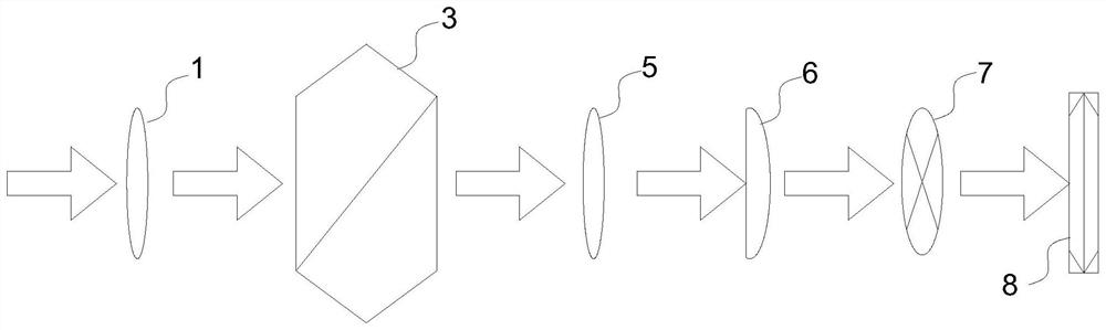
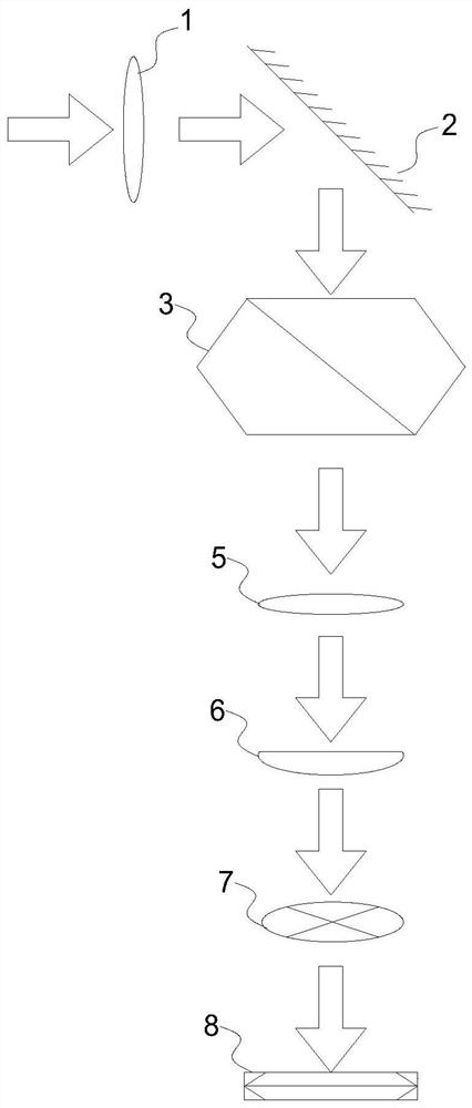
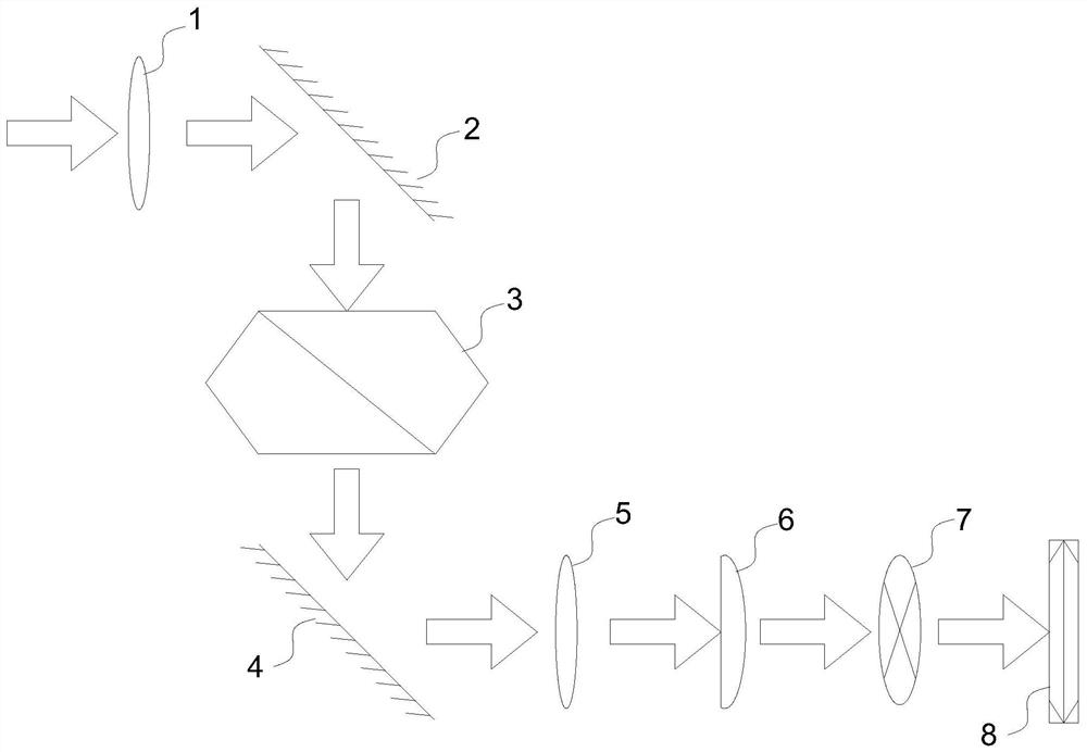
[0038] A unit-detector optical tomography time-division modulation imaging system proposed in this embodiment includes an image rotation device 3, a cylindrical mirror 6, and an imaging detector 8 arranged sequentially along the front direction of the imaging surface of the object to be imaged, namely The object to be imaged, the image rotating device 3 , the cylindrical mirror 6 and the imaging detector 8 are sequentially arranged along the direction of light propagation, and in the direction of light propagation, the imaging surface of the obje...


PUM

PropertyMeasurementUnit
Diameteraaaaaaaaaa

Abstract

A unit detector optical tomography time division modulation imaging system comprises an image rotating device, a cylindrical mirror and an imaging detector which are sequentially arranged in the front direction of an imaging face of an object to be imaged. The image rotating device is used for rotating an incident object image to generate a rotating image; the cylindrical mirror is used for performing one-dimensional integral amplification on an incident rotating image; and the imaging detector is used for collecting the rotating image after one-dimensional integral amplification of the cylindrical mirror. According to the invention, one-dimensional integration is carried out on the optical signal through the cylindrical mirror, so that signal enhancement of the optical signal is realized, that is, pixel value improvement is carried out on a rotating image passing through the cylindrical mirror in the integration direction. Through the cooperation of the cylindrical mirror and the imaging detector, the reflected light of the object to be imaged is equivalently subjected to secondary integration, so that the pixels of the rotating image obtained by the imaging detector are easier to distinguish, and the finally obtained reconstructed two-dimensional image of the object to be imaged is clearer.

Description

technical field [0001] The invention relates to the imaging field, in particular to a unit detector optical tomography scanning time-division modulation imaging system. Background technique [0002] Object detection and tracking is a research topic of great interest to people all the time. In order to pursue a better target detection effect, the detection of target imaging technology has always attracted much attention. Existing imaging detection devices are mostly used in parallel light environments, and the resolution in natural light environments is far from ideal. Contents of the invention [0003] In order to solve the defect that the resolution of the imaging detection device in the prior art is not ideal in the natural light environment, the present invention proposes a unit detector optical tomography time division modulation imaging system. [0004] The object of the present invention adopts following technical scheme: [0005] A unit detector optical tomograph...

Claims


Application Information

Patent Timeline
IPC IPC(8): H04N5/225H04N5/217H04N5/232
CPCH04N23/81H04N23/54H04N23/50H04N23/55H04N23/80H04N23/695
Inventor 李保生韩宝坤
Owner HEFEI UNIV OF TECH
Why Eureka
Try Eureka