Leg stretching device for physical fitness

A leg and sports technology, applied in gymnastics equipment, sports accessories, etc., can solve problems such as single-level stretching and protection of people who cannot exercise, and achieve the effect of increasing strength

Active Publication Date: 2021-06-01
SHAANXI SCI TECH UNIV
View PDF4 Cites 0 Cited by
  • Summary
  • Abstract
  • Description
  • Claims
  • Application Information

AI Technical Summary

Problems solved by technology

[0002] In order to increase the flexibility of the joints, it is necessary to stretch the legs. At present, when the legs are stretched, it is usually manually pressed and stretched on the legs of the exerciser, especially when performing dance exercises. , to train this, first perform the downward split stretching training during stretching. When the strength of the

Method used


Image

  • Leg stretching device for physical fitness
  • Leg stretching device for physical fitness
  • Leg stretching device for physical fitness

Examples


Embodiment 1

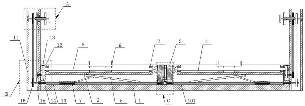
[0033] Such as figure 1 The shown leg stretching device for physical fitness includes a base 1 with a groove, and the middle part of the groove in the base 1 is provided with a spacer 3 that divides the groove into a left cavity and a right cavity , the left cavity and the right cavity are respectively provided with a left angle adjustment seat 2 and a right angle adjustment seat 4, and the ends of the left angle adjustment seat 2 and the right angle adjustment seat 4 are respectively connected to the two ends of the spacer 3 Hinged; the ends of the left angle adjustment seat 2 and the right angle adjustment seat 4 are provided with T-shaped connectors, and the two T-shaped connectors are respectively inserted into the U-shaped connectors at both ends of the spacer 3 and passed through the shaft It is movably connected to ensure that the left angle adjustment seat 2 and the right angle adjustment seat 4 can rotate along the spacer 3, and the left angle adjustment seat 2 and th...

Embodiment 2

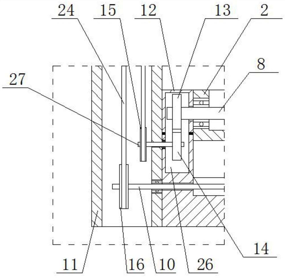
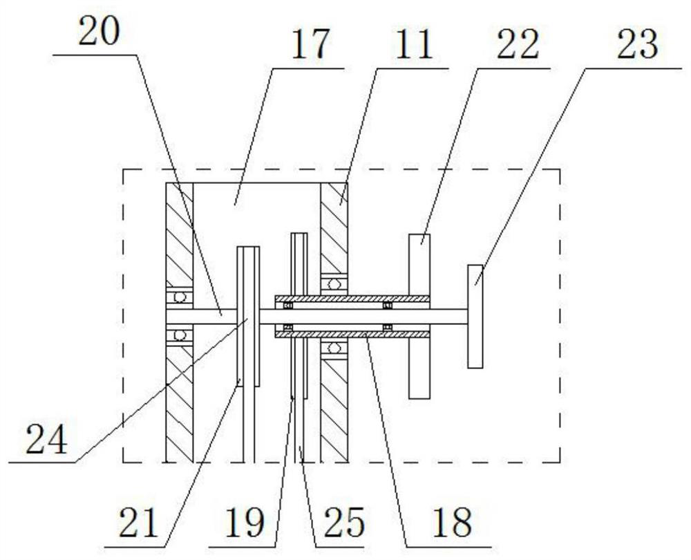
[0044] On the basis of Embodiment 1, in order to ensure that the first drive assembly and the second drive assembly can be driven stably, as figure 2 The first driving assembly includes a second driven gear 15 disposed in the cavity 17, the second driven gear 15 is fixedly connected to the end of the first rotating shaft 27, and the upper part of the side plate 11 is provided with The first driving shaft 18, one end of the first driving shaft 18 extends to the cavity 17 and the second driving gear 19 provided in the cavity 17, the second driving gear 19 and the second driven gear 15 pass through The first chain 25 links; the other end of the first drive shaft 18 is fixed with a first drive wheel 22;

[0045] The second drive assembly includes a third driven gear 16 fixedly connected to the left drive screw 10 / right drive screw 101 at the lower end of the cavity 17, and the second drive shaft 20 is movably connected to the upper part of the side plate 11 , one end of the seco...

Embodiment 3

[0050] On the basis of Embodiment 1, in order to ensure that the angles of the left adjustment base and the right adjustment base can be adjusted synchronously or independently; the centerlines of the left driving screw 10 and the right driving screw 101 are located on the same horizontal line.

[0051] Such as Figure 4 The spacer 3 is provided with a square through hole 301 extending from top to bottom, and the square through hole 301 communicates with the connection cavity 302 provided in the bottom of the spacer 3 , and the lower part of the direction through hole 301 is provided with a slider 304 is movably connected with the slide rail 307 arranged in the square through hole 301, and the slider 304 is fixedly connected with the bearing seat 308 arranged in the connection cavity 302 through a vertical connecting rod, and a vertical rotation is arranged in the said direction through hole 301. Leading screw 305, the lower end of this vertically rotating leading screw 305 pa...


PUM


Abstract

The invention relates to a leg stretching device for physical fitness, which comprises a base and a spacer arranged in the middle of a groove in the base, a left angle adjusting seat and a right angle adjusting seat are arranged in a left cavity and a right cavity respectively, and a left driving lead screw and a right driving lead screw are arranged at the bottom of the left cavity and the bottom of the right cavity respectively. A supporting rod is hinged to the left angle adjusting seat and the right angle adjusting seat, and the driving body is movably connected with the middle of the supporting rod through a connecting rod; rotating lead screws are movably connected in the left angle adjusting seat and the right angle adjusting seat respectively, and are in threaded connection with foot stands arranged in the left angle adjusting seat/the right angle adjusting seat; the rotating lead screws are connected with the first driving assembly, and the left driving lead screw and the right driving lead screw are connected with the second driving lead screw. According to the invention, horizontal tendon stretching can be stably carried out, angle tendon stretching can be carried out after horizontal tendon stretching (splitting) is completed, the exercise strength is improved, the tendon stretching speed can be effectively controlled during exercise, and an exerciser can be effectively protected.

Description

technical field [0001] The invention relates to the technical field of physical fitness, in particular to a leg stretching device for physical fitness. Background technique [0002] In order to increase the flexibility of the joints, it is necessary to stretch the legs. At present, when the legs are stretched, the legs of the exerciser are usually pressed and stretched manually, especially when performing dance exercises. , to train this, first perform the downward split stretching training during stretching. When the strength of the stretching needs to be strengthened after the downward splitting and parallel stretching is completed, the lower stretching training needs to be performed at an angle exceeding the horizontal stretching , and the current stretching device can only perform single horizontal stretching, and cannot effectively protect the people taking exercise during the stretching process. Contents of the invention [0003] In order to overcome the above-menti...

Claims


Application Information

Patent Timeline
IPC IPC(8): A63B23/04
CPCA63B23/0488
Inventor 张妮贺雅奇
Owner SHAANXI SCI TECH UNIV
Why Eureka
Try Eureka