Industrial steel pipe bending device

A bending device, industrial technology, applied in the direction of feeding device, positioning device, storage device, etc., can solve the problem of failure to realize automatic discharge, and achieve the effect of reducing the time of manual receiving

Active Publication Date: 2021-06-01
安徽泓鞍机械制造有限公司
View PDF7 Cites 1 Cited by
  • Summary
  • Abstract
  • Description
  • Claims
  • Application Information

AI Technical Summary

Problems solved by technology

[0004] In order to overcome the shortcomings that the workers use simple bending equipment to bend the steel pipe, the steel pipe will not automatically fall after bending, and the steel pipe needs to be manually taken out of the bending equipment, and the function of automatic discharge cannot be realized. The technical problem to be solved: provide an industrial steel pipe bending device capable of automatic discharge, automatic collection and convenient operation

Method used


Image

  • Industrial steel pipe bending device
  • Industrial steel pipe bending device
  • Industrial steel pipe bending device

Examples


Embodiment 1

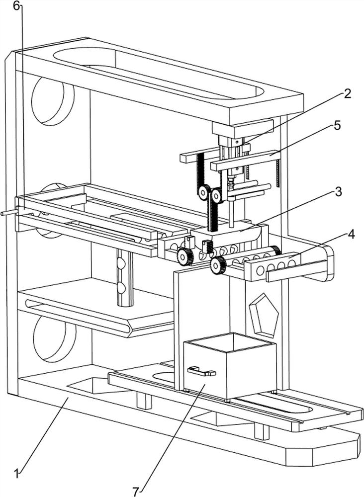
[0027] An industrial steel pipe bending device, such as figure 1 As shown, it includes a first support frame 1, a cylinder 2, a pressing mechanism 3 and a bending mechanism 4, the upper right side of the first support frame 1 is equipped with a cylinder 2, and the upper right side of the first support frame 1 is connected with the cylinder 2. A pressing mechanism 3 is arranged between them, and a bending mechanism 4 is arranged between the middle of the right part of the first support frame 1 and the pressing mechanism 3 .

[0028] When people need to bend steel pipes, this industrial steel pipe bending device can be used. First, people need to put the steel pipes into the bending mechanism 4, then start the cylinder 2, and the telescopic rod of the cylinder 2 moves up and down to drive the pressing mechanism 3 Move up and down, bend the steel pipe, close the cylinder 2 after bending, and people can collect it on the lower side.

Embodiment 2

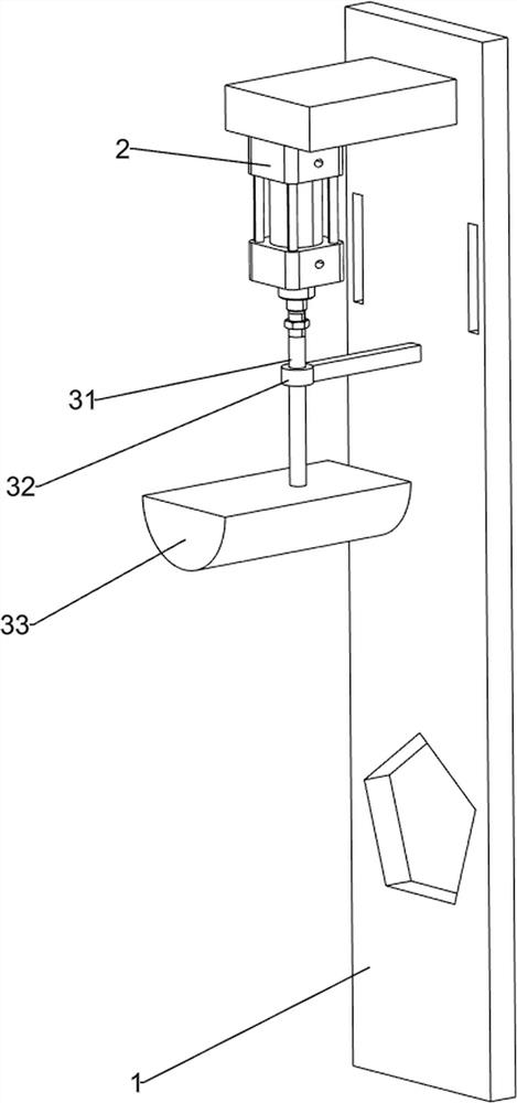
[0030] On the basis of Example 1, such as Figure 2-Figure 6 As shown, the pressing mechanism 3 includes a first support column 31, a spacer 32 and a U-shaped hammer 33. The upper side of the right part of the first support frame 1 is provided with a spacer 32, and the front side of the spacer 32 is slidingly provided with a The first support column 31, the top of the first support column 31 is connected with the telescopic rod of the cylinder 2, and the bottom of the first support column 31 is provided with a U-shaped hammer 33.

[0031] People put the steel pipe in the bending mechanism 4, then start the cylinder 2, and the telescopic rod of the cylinder 2 moves downward to drive the first support column 31 to move downward, thereby driving the U-shaped hammer 33 to move downward to press down on the steel pipe. When the telescoping link of cylinder 2 moves upwards and drives first support column 31 to move upwards, first support column 31 drives U-shaped hammer 33 to move u...


PUM


Abstract

The invention relates to a bending device, in particular to an industrial steel pipe bending device. The invention provides the industrial steel pipe bending device which can achieve automatic discharging and automatic collecting and is convenient to operate. The industrial steel pipe bending device comprises a first supporting frame, an air cylinder, a downward pressing mechanism, a bending mechanism and the like; and the air cylinder is installed on the upper side of the right portion of the first supporting frame, the downward pressing mechanism is arranged between the upper side of the right portion of the first supporting frame and the air cylinder, and the bending mechanism is arranged between the middle of the right portion of the first supporting frame and the downward pressing mechanism. According to the industrial steel pipe bending device, a telescopic rod of the air cylinder moves downwards to drive a first supporting column to move downwards, so that a U-shaped hammer is driven to move downwards to press a steel pipe downwards, thereby achieving the pressing effect; and a first rack moves downwards to drive a first straight gear on the front side to rotate, so that first rotating shafts are driven to rotate, then first fixing frames are driven to turn inwards to bend the steel pipe, and the bending effect is achieved.

Description

technical field [0001] The invention relates to a bending device, in particular to an industrial steel pipe bending device. Background technique [0002] Steel pipes can be used to convey fluids and powdery solids, and manufacture mechanical parts and containers. Steel can also save investment and maintenance costs. Steel pipes can replace part of the manufacturing materials. Steel pipes are also used in our lives. For example, the manufacture of agricultural machinery, ventilation equipment, underground energy development, and drainage equipment are all inseparable from steel pipes. In industrial manufacturing, the manufacture of steel pipes is very common. Many steel pipes need to be bent. However, at present, in some factories, workers use simple bending equipment to bend steel pipes. After bending, steel pipes will not fall automatically. It is necessary to manually take out the steel pipe from the bending equipment, and the function of automatic discharge cannot be rea...

Claims


Application Information

Patent Timeline
Patent Type & Authority Applications(China)
IPC IPC(8): B21D7/024B21D43/00B21D43/04B21D43/20
CPCB21D7/024B21D43/003B21D43/04B21D43/20Y02P70/10
Inventor 陈玉梅
Owner 安徽泓鞍机械制造有限公司
Why Eureka
Try Eureka