A press-type clay tile forming device
A molding device and clay technology, which is applied in the directions of molding indenters, unloading devices, ceramic molding machines, etc., can solve the problems of unsafe, consume a lot of physical force, press down, cut and shape, and achieve the effect of convenient collection.
- Summary
- Abstract
- Description
- Claims
- Application Information
AI Technical Summary
Problems solved by technology
Method used
Image
Examples
Embodiment 1
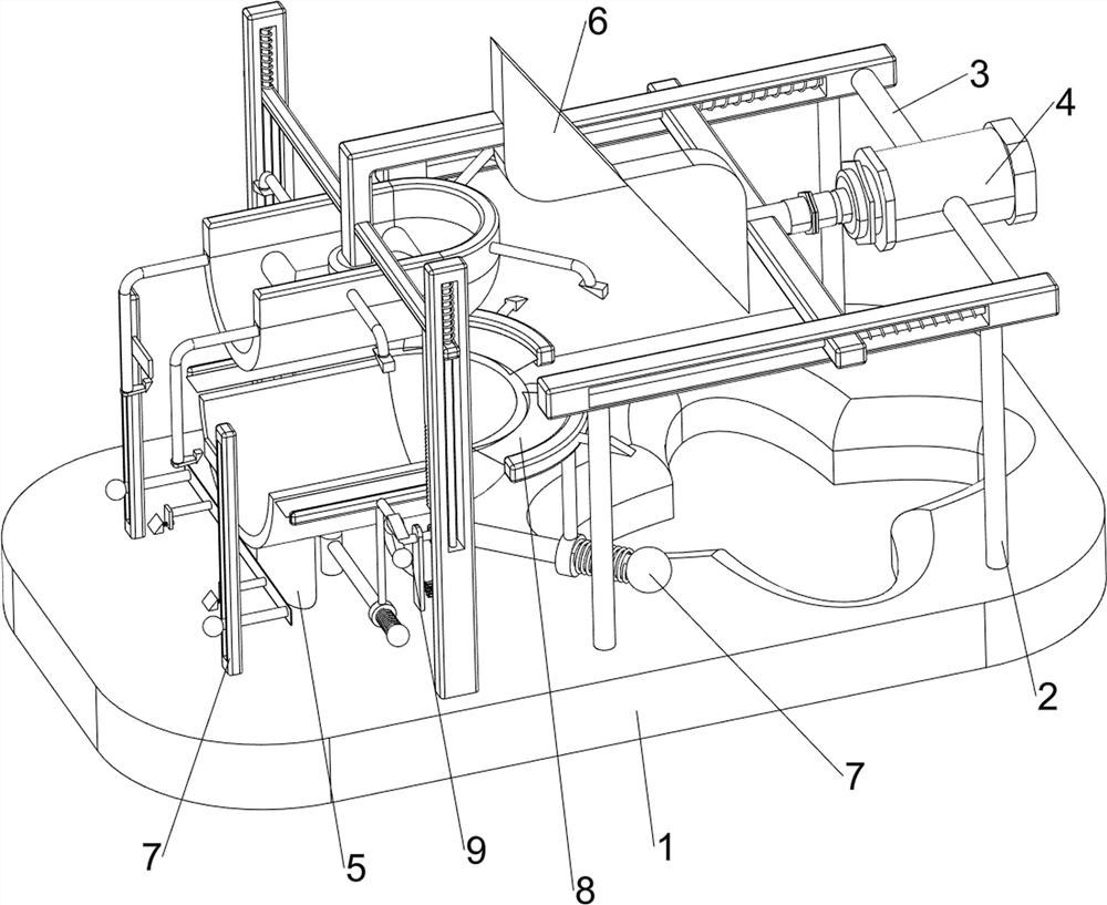
[0024] A down-pressing clay tile forming device, such as figure 1 As shown, it includes a base 1, a support column 2, a first connection block 3, a cylinder 4, a mold 5 and a pressing mechanism 6. Two support columns 2 are provided on the front and rear sides of the base 1, and the left side of the base 1 is provided with There is a mold 5, a pressing mechanism 6 is provided between the tops of the four support columns 2 and on the left side of the base 1, a first connecting block 3 is connected to the right side of the pressing mechanism 6, and a cylinder 4 is installed in the middle of the first connecting block 3, The cylinder 4 is connected to the pressing mechanism 6 .
[0025] When people need to shape clay tiles, they can use this molding device. First, people put the clay into the mold 5, and then open the air cylinder 4. The air cylinder 4 drives the pressing mechanism 6 to press down the clay. After molding, people remove the molding. Then, the cylinder 4 is closed ...
Embodiment 2
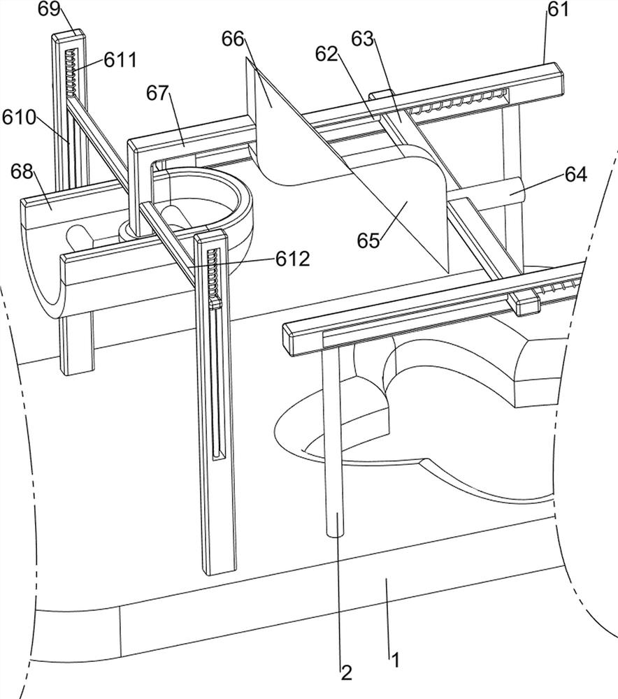
[0027] On the basis of Example 1, as figure 2 As shown, the pressing mechanism 6 includes a first guide rail 61, a first guide rod 62, a first sliding block 63, a second connecting block 64, a first wedge-shaped block 65, a second wedge-shaped block 66, a third connecting block 67, The pressing block 68, the second guide rail 69, the second guide rod 610, the first spring 611 and the second slider 612, the first guide rail 61 is connected between the tops of the two support columns 2 on the front and rear sides, and the two first The right side of the guide rail 61 is connected by the first connecting block 3 , the two first guide rails 61 are provided with first guide rods 62 , and a first sliding block 63 is slidably connected between the two first guide rods 62 . The middle part of the block 63 is provided with a second connecting block 64 , the left part of the second connecting block 64 is provided with a first wedge block 65 , and the front and rear parts on the left si...
Embodiment 3
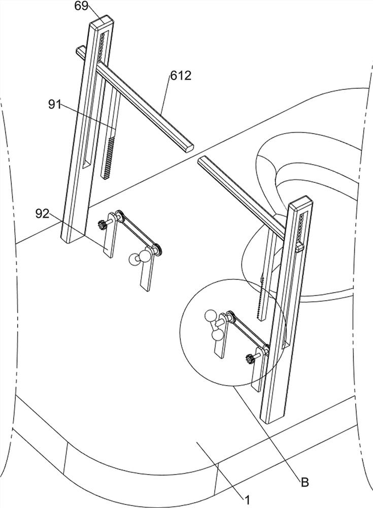
[0030] On the basis of Example 2, as image 3 , Figure 4 , Figure 5 , Image 6 and Figure 7 As shown, a vertical cutting mechanism 7 is also included, and a vertical cutting mechanism 7 is provided on the pressing block 68 and on the left side of the base 1. The vertical cutting mechanism 7 includes a first blade 71, a fourth connecting block 72, and a third wedge-shaped block 73 , the third slide rail 74, the third guide rod 75, the second spring 76, the third slider 77, the second blade 78, the fifth connecting block 79, the fourth guide rod 710, the third spring 711 and the fourth wedge block 712, both the front and rear walls on the right side of the pressure block 68 are provided with a first blade 71, the left wall of the pressure block 68 is provided with a fourth connection block 72 at the front and rear, and the bottom of the two fourth connection blocks 72 are provided with a third wedge-shaped block 73. Third slide rails 74 are provided on both the front and ...
PUM
 Abstract
Description
Claims
Application Information
 - R&D
- Intellectual Property
- Life Sciences
- Materials
- Tech Scout
- Unparalleled Data Quality
- Higher Quality Content
- 60% Fewer Hallucinations
Browse by: Latest US Patents, China's latest patents, Technical Efficacy Thesaurus, Application Domain, Technology Topic, Popular Technical Reports.
© 2025 PatSnap. All rights reserved.Legal|Privacy policy|Modern Slavery Act Transparency Statement|Sitemap|About US| Contact US: help@patsnap.com


