Auxiliary cutting treatment device for longitudinal cutting line

A processing device and slitting line technology, which is applied in woodworking safety devices, forming/shaping machines, springs/shock absorbers, etc., can solve the problems of large cutting errors of plank deviation and great danger to operators, etc.

Active Publication Date: 2022-03-08
深圳市宇旺模具有限公司
View PDF5 Cites 0 Cited by
  • Summary
  • Abstract
  • Description
  • Claims
  • Application Information

AI Technical Summary

Problems solved by technology

[0004] In order to overcome the disadvantages of the existing hand-clamped method of cutting wood boards, which tends to cause large deviations in the cutting of the wood boards and cause great danger to the operator, the technical problem of the present invention is to provide a fast clamping board, and A slitting line auxiliary cutting device that can quickly adjust the cutting distance and angle of the wood board and can absorb shock and cool down

Method used


Image

  • Auxiliary cutting treatment device for longitudinal cutting line
  • Auxiliary cutting treatment device for longitudinal cutting line
  • Auxiliary cutting treatment device for longitudinal cutting line

Examples


Embodiment 1

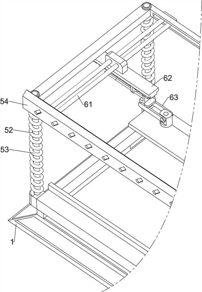
[0078] A slitting line auxiliary cutting processing device, such as figure 1 , figure 2 , image 3 , Figure 4 , Figure 5 , Image 6 , Figure 7 , Figure 8 , Figure 9 , Figure 10 and Figure 15 As shown, it includes a support frame 1, a motor 2, a cutting knife 3, a clamping mechanism 4, a lifting mechanism 5, a distance adjustment mechanism 6, a cutting angle adjustment mechanism 7 and a shock absorbing mechanism 10, and the support frame 1 is provided with a clamping mechanism 4. There is a lifting mechanism 5 on the top of the support frame 1, and the lifting mechanism 5 cooperates with the clamping mechanism 4. The lifting mechanism 5 is provided with a distance adjustment mechanism 6, and the distance adjustment mechanism 6 is provided with a cutting angle adjustment mechanism 7. 7 is provided with shock absorbing mechanism 10, and shock absorbing mechanism 10 cooperates with distance adjustment mechanism 6, and shock absorbing mechanism 10 is provided with ...

Embodiment 2

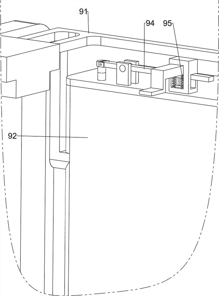
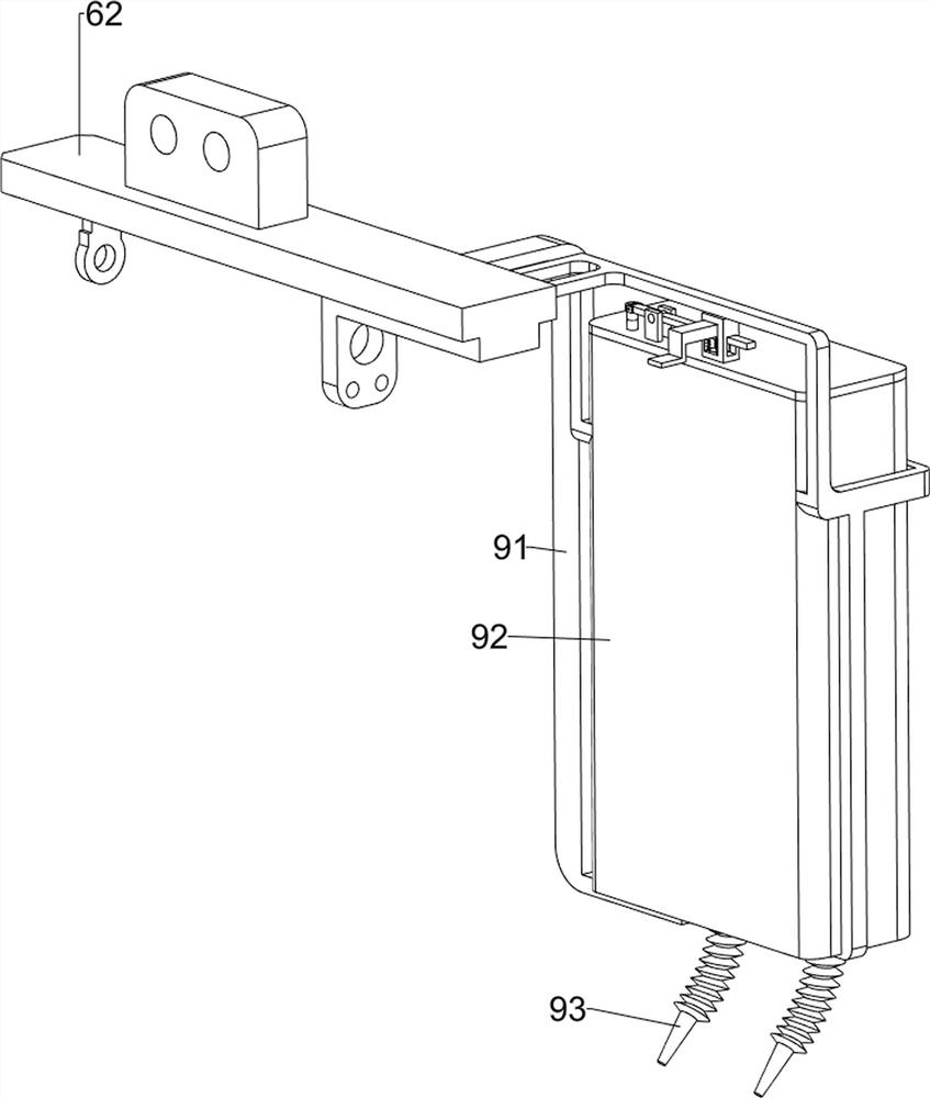
[0091] On the basis of Example 1, such as figure 1 , figure 2 , image 3 , Figure 11 , Figure 12 , Figure 13 and Figure 14 As shown, it also includes a pressing mechanism 8, and the pressing mechanism 8 includes a fixed frame 81, a moving frame 82, a fourth spring 83, a rack bar 84, a fifth spring 85 and a gear rod 86, and the second sliding frame 62 front The left side of the part is provided with a fixed frame 81, and the rear side sliding type in the fixed frame 81 is provided with a movable frame 82, and a fourth spring 83 is wound on the movable frame 82, and the two ends of the fourth spring 83 are connected with the fixed frame 81 and the movable frame 82 respectively. Connection, fixed frame 81 top sliding type is provided with rack bar 84, and the rear end of rack bar 84 contacts and cooperates with moving frame 82, is connected with the fifth spring 85 between the middle part of rack bar 84 and fixed frame 81, and the front of fixed frame 81 The side-rotat...


PUM


Abstract

The invention relates to a cutting device, in particular to an auxiliary cutting treatment device for a longitudinal cutting line. According to the auxiliary cutting treatment device for the longitudinal cutting line, a wood board can be rapidly clamped, the cutting distance and angle of the wood board can be rapidly adjusted, and damping and cooling can be achieved. The auxiliary cutting treatment device for the longitudinal cutting line comprises a supporting frame and a clamping mechanism, and the clamping mechanism is arranged on the supporting frame; the lifting mechanism is arranged at the top of the supporting frame, and the lifting mechanism is matched with the clamping mechanism; the distance adjusting mechanism is arranged on the lifting mechanism; and the cutting angle adjusting mechanism is arranged on the distance adjusting mechanism. Through the arrangement of the clamping mechanism, a clamping device rotates to rapidly clamp a wood board, and the rapid and automatic clamping effect is achieved; and the downward pressing mechanism is arranged, so that the downward pressing effect can be achieved without manually pressing the connecting shaft downwards.

Description

technical field [0001] The invention relates to a cutting device, in particular to an auxiliary cutting processing device for a slitting line. Background technique [0002] Wood is the main raw material in wooden furniture, but most of the wood in wooden furniture is in the form of plates. Most of the wood cutting devices used in furniture production and processing do not have a device for clamping the wood during the processing of the plates. Only the operator pushes the wood with his hands to cut. This method of clamping the wood to cut the wood is very complicated. It is also dangerous to the operator, and at the same time, the cutting error is relatively large, which reduces the cutting efficiency of the plate. [0003] For this reason, we propose a slitting line auxiliary cutting processing device that can quickly clamp the wood board, quickly adjust the cutting distance and angle of the wood board, and can absorb shock and cool down. Contents of the invention [00...

Claims


Application Information

Patent Timeline
IPC IPC(8): B27C5/02B27C5/06B27G21/00F16F15/067
CPCB27C5/02B27C5/06B27G21/00F16F15/067Y02E60/10
Inventor 周彩红
Owner 深圳市宇旺模具有限公司
Why Eureka
Try Eureka