Automatic rivet supply riveting machine

A riveting machine and nail feeding technology, applied in the field of riveting machines, can solve problems such as rivets falling down, rivets not coming out normally, and affecting the riveting of luggage, etc., so as to speed up the riveting speed, reduce the rivets stuck inside the opening, and speed up speed effect

Inactive Publication Date: 2021-06-01
曾爱民
View PDF5 Cites 0 Cited by
  • Summary
  • Abstract
  • Description
  • Claims
  • Application Information

AI Technical Summary

Problems solved by technology

[0002] In the process of processing luggage, the riveting machine is used to rivet and connect different parts, and the rivet is added to the riveter of the riveting machine, and the rivet falls down along the riveting tube, and the motor drives the riveting tube to rotate at high speed to rive the rivet on the Luggage surface: in the prior art, when riveting the luggage with a riveting machine, since different rivets are used for processing different luggage, and the inner diameter of the riveting tube is uniform, when the volume of the rivet is small, it is easy for two rivets to fall down at the same time fall, and get stuck inside the riveting tube, causing the rivet not to come out normally, affecting the normal riveting of the bag by the riveting machine

Method used


Image

  • Automatic rivet supply riveting machine
  • Automatic rivet supply riveting machine
  • Automatic rivet supply riveting machine

Examples


Embodiment 1

[0025] as attached figure 1 to attach Figure 5 Shown:

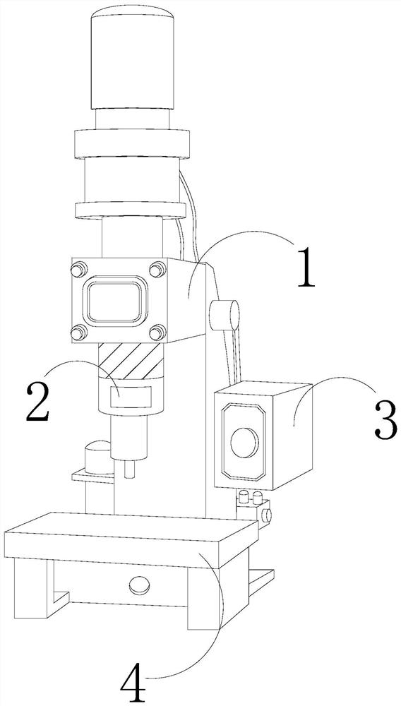
[0026] The invention provides an automatic nail feeding riveting machine, the structure of which includes a body 1, a riveter 2, a control box 3, and a workbench 4. The riveter 2 is installed on the front bottom of the body 1, and the control box 3 is arranged on On the right side of the body 1, the workbench 4 is located below the riveter 2.

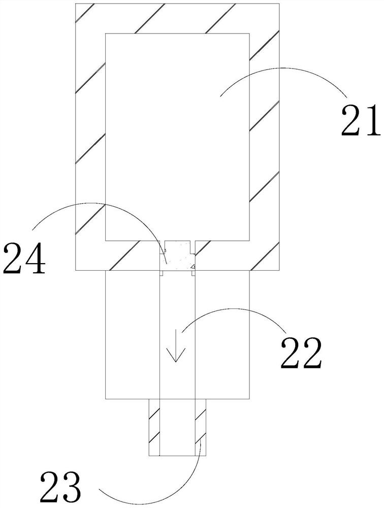
[0027] The riveter 2 is provided with a nail collection chamber 21, a nail groove 22, a riveting tube 23, and a guide mechanism 24. The nail collection chamber 21 is located at the inner top of the riveter 2, and the riveting tube 23 is vertically fixed on the riveting The middle part of the bottom surface of the stapler 2, the nail groove 22 is connected between the nail collecting cavity 21 and the riveting tube 23, and the guide mechanism 24 is sleeved on the top end of the nail groove 22.

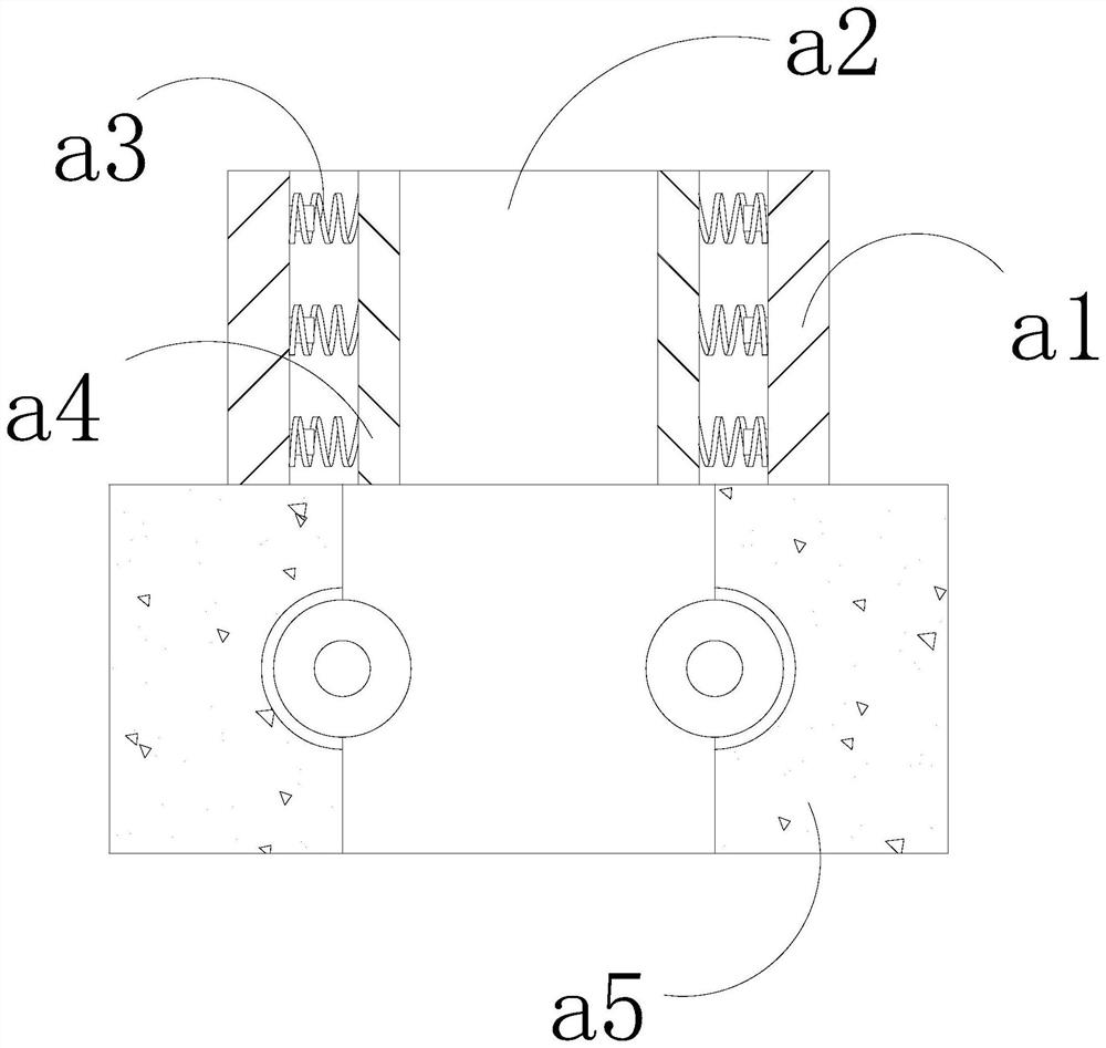
[0028] Wherein, the guide mechanism 24 is provided with a support ring a1, an openin...

Embodiment 2

[0034] as attached Figure 6 to attach Figure 7 Shown:

[0035] Wherein, the push mechanism a5 is provided with a drainage groove r1, a push ring r2, and a support rod r3, the drainage groove r1 runs through the upper and lower surfaces of the middle part of the push mechanism a5, and the push ring r2 is connected and installed on the inner wall of the drainage groove r1 through the support rod r3 In the middle position, there are two push rings r2, which can increase the contact area between the push ring r2 and the rivet, increase the driving force on the rivet, and accelerate the falling speed of the rivet.

[0036] Wherein, the push ring r2 is provided with a support shaft t1, a swing block t2, a joint shaft t3, and a push bar t4, the support shaft t1 is located in the middle of the push ring r2, and the swing block t2 is connected and installed on the support shaft through the joint shaft t3 The outer wall of t1, the push bar t4 is sandwiched between the swinging block...


PUM


Abstract

The invention discloses an automatic rivet supply riveting machine which structurally comprises a machine body, a riveting device, a control box and a workbench. The riveting device is installed at the bottom of the front face of the machine body, the control box is arranged on the right side of the machine body, and the workbench is located below the riveting device. Due to the fact that the size of rivets is small, the phenomenon that two rivets fall down at the same time is likely to happen, the diameter between ring bodies of an expansion ring of a guide mechanism is changed along with the sizes of the rivets, so that it is ensured that only one rivet falls down when the rivets are discharged every time, the phenomenon that two rivets fall down simultaneously and are clamped in a riveting pipe is reduced, normal rivet discharging is facilitated, and the riveting machine can rivet bags normally; and due to the fact that the outer walls of part of the rivets are uneven, the friction force between the rivets and limiting blocks is increased, the rivets are likely to be clamped between the limiting blocks, the rivets are pushed downwards through rotation of a pushing ring in a pushing mechanism, the falling speed of the rivets can be increased, the situation that the rivets are clamped in an opening is reduced, and the speed of riveting luggage through the riveting pipe is further increased.

Description

technical field [0001] The invention belongs to the field of riveting machines, and more specifically, relates to an automatic feeding riveting machine. Background technique [0002] In the process of processing luggage, the riveting machine is used to rivet and connect different parts, and the rivet is added to the riveter of the riveting machine, and the rivet falls down along the riveting tube, and the motor drives the riveting tube to rotate at high speed to rive the rivet on the Luggage surface: in the prior art, when riveting the luggage with a riveting machine, since different rivets are used for processing different luggage, and the inner diameter of the riveting tube is uniform, when the volume of the rivet is small, it is easy for two rivets to fall down at the same time Fall, and get stuck inside the riveting tube, causing the rivet not to be nailed normally, affecting the normal riveting of the bag by the riveting machine. Contents of the invention [0003] In...

Claims


Application Information

Patent Timeline
Patent Type & Authority Applications(China)
IPC IPC(8): B21J15/32
CPCB21J15/32
Inventor 曾爱民
Owner 曾爱民
Why Eureka
Try Eureka