Plywood cutting mechanism

A cutting mechanism, a technology for plywood, applied in metal processing and other directions, can solve problems such as low sawing efficiency

Active Publication Date: 2021-06-01
贵港市明弘木业有限公司
View PDF13 Cites 1 Cited by
  • Summary
  • Abstract
  • Description
  • Claims
  • Application Information

AI Technical Summary

Problems solved by technology

However, the general cutting mechanism needs to separate the chainsaw cutting and the wire saw cutting, resulting in low sawing efficiency

Method used


Image

  • Plywood cutting mechanism
  • Plywood cutting mechanism
  • Plywood cutting mechanism

Examples


Embodiment Construction

[0024] In order to make the object, technical solution and advantages of the present invention clearer, the present invention will be further described in detail below in conjunction with the accompanying drawings and embodiments. It should be understood that the specific embodiments described here are only used to explain the present invention, not to limit the present invention.

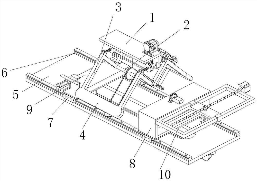
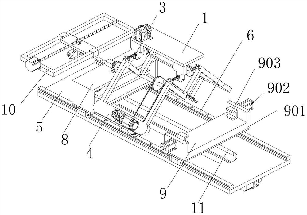
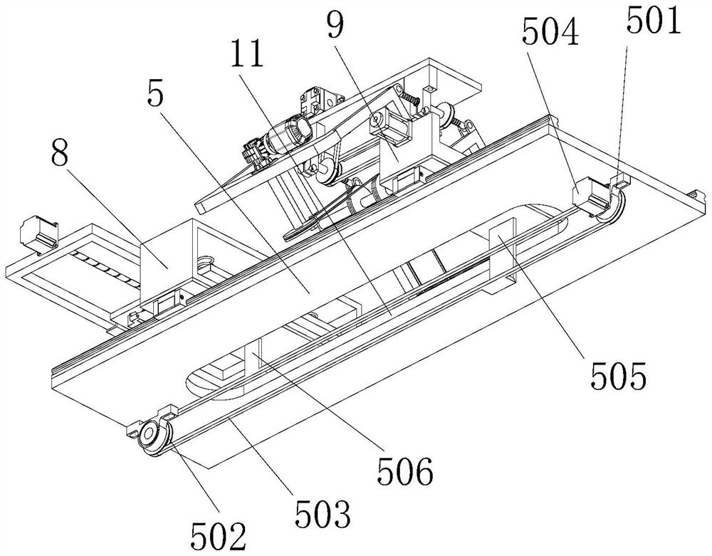
[0025] refer to Figure 1 to Figure 8A plywood cutting mechanism shown includes a carrying board 5 , and the carrying board 5 is independently and fixedly installed, for example fixedly installed relative to the ground. The top of the carrying plate 5 is fixedly installed with two propelling guide rails 6, and each propelling guide rail 6 is provided with two propelling sliders 7, and the propelling sliders 7 are slidably connected with the propelling guide rails 6, and the corresponding propelling sliders on every two propelling guide rails Blocks 7 form a group, wherein a locking assembly 8 is f...


PUM


Abstract

The invention discloses a plywood cutting mechanism, and belongs to the field of plywood processing. The plywood cutting mechanism comprises a carrying plate, and the carrying plate is independently and fixedly installed; the top end of the carrying plate is fixedly provided with two propulsion guide rails, and two propulsion sliding blocks are arranged on the propulsion guide rails; the propulsion sliding blocks are slidably connected with the propulsion guide rails; a round rod penetrating through the inner side of a bottom axle bed is arranged on one side of each carrying roller, and the carrying rollers are rotationally connected with the bottom axle bed; and one carrying roller is installed at the output end of a carrying motor. The plywood cutting mechanism is high in saw cutting efficiency.

Description

technical field [0001] The invention relates to the technical field of cutting, in particular to a plywood cutting mechanism. Background technique [0002] In the field of plywood processing, cutting equipment is required. When cutting plywood, a saw blade is required for processing, and a wire saw is required for edge cutting, and the weight of the wire saw is relatively light, and it is relatively simple to store. For the cutting of the ends, a chainsaw is required. However, the general cutting mechanism needs to separate the electric saw cutting and the wire saw cutting for implementation, resulting in low sawing efficiency. Contents of the invention [0003] The object of the present invention is to provide a cutting mechanism for plywood aiming at the deficiencies of the prior art. A cutting mechanism for plywood, comprising a carrying board, which is independently fixed and installed, two pushing guide rails are fixedly installed on the top of the carrying board, t...

Claims


Application Information

Patent Timeline
Patent Type & Authority Applications(China)
IPC IPC(8): B26D9/00B26D1/18B26D1/48B26D7/02B26D7/06B26D7/26
CPCB26D9/00B26D1/18B26D1/48B26D7/025B26D7/0608B26D7/2628
Inventor 刘夫贵
Owner 贵港市明弘木业有限公司
Why Eureka
Try Eureka