
Turnout control circuit and turnout control system

A technology for controlling circuits and turnouts, which is applied in the direction of electrical equipment, railway signals, railway car body components, etc. used to control turnouts or line breakers. The amount of installation and the difficulty of installation, the control logic is clear and simple, and the effect of reducing interactive nodes

Active Publication Date: 2022-05-13
BYD CO LTD
View PDF7 Cites 0 Cited by
  • Summary
  • Abstract
  • Description
  • Claims
  • Application Information

AI Technical Summary

Problems solved by technology

[0005] 1. The position of the turnout depends on the limit baffle on the turnout touching the limit switch to trigger the output signal of the contact closure of the limit switch. This method relies on mechanical collision, which will cause great damage to the equipment and will affect the equipment after long-term wear. Accuracy; and, because the limit switch is installed outdoors without any protective measures, it is easily affected by external factors, such as human error, falling objects, etc.
[0006] 2. When the turnout performs unlocking and locking actions, the limit switch first needs to send the position information to the turnout control system. After the turnout system handles it, the locking circuit controls the locking motor to execute. This method needs to be set at each position Travel switch, the logic is more cumbersome, the circuit design is more complicated; moreover, there are many wiring harnesses in actual engineering applications, equipment installation and maintenance are difficult, and the cost is high;
[0007] Third, it is not conducive to the development of rail transit intelligence, informatization and lightweight

Method used


Image

  • Turnout control circuit and turnout control system
  • Turnout control circuit and turnout control system
  • Turnout control circuit and turnout control system

Examples


Embodiment Construction

[0070] In order to make the objects, technical solutions and advantages of the present invention more apparent, exemplary embodiments according to the present invention will be described in detail below with reference to the accompanying drawings. Apparently, the described embodiments are only some embodiments of the present invention, rather than all embodiments of the present invention, and it should be understood that the present invention is not limited by the exemplary embodiments described here. Based on the embodiments of the present invention described in the present invention, all other embodiments obtained by those skilled in the art without creative effort shall fall within the protection scope of the present invention.

[0071] In the following description, numerous specific details are given in order to provide a more thorough understanding of the present invention. It will be apparent, however, to one skilled in the art that the present invention may be practiced...


PUM


Abstract

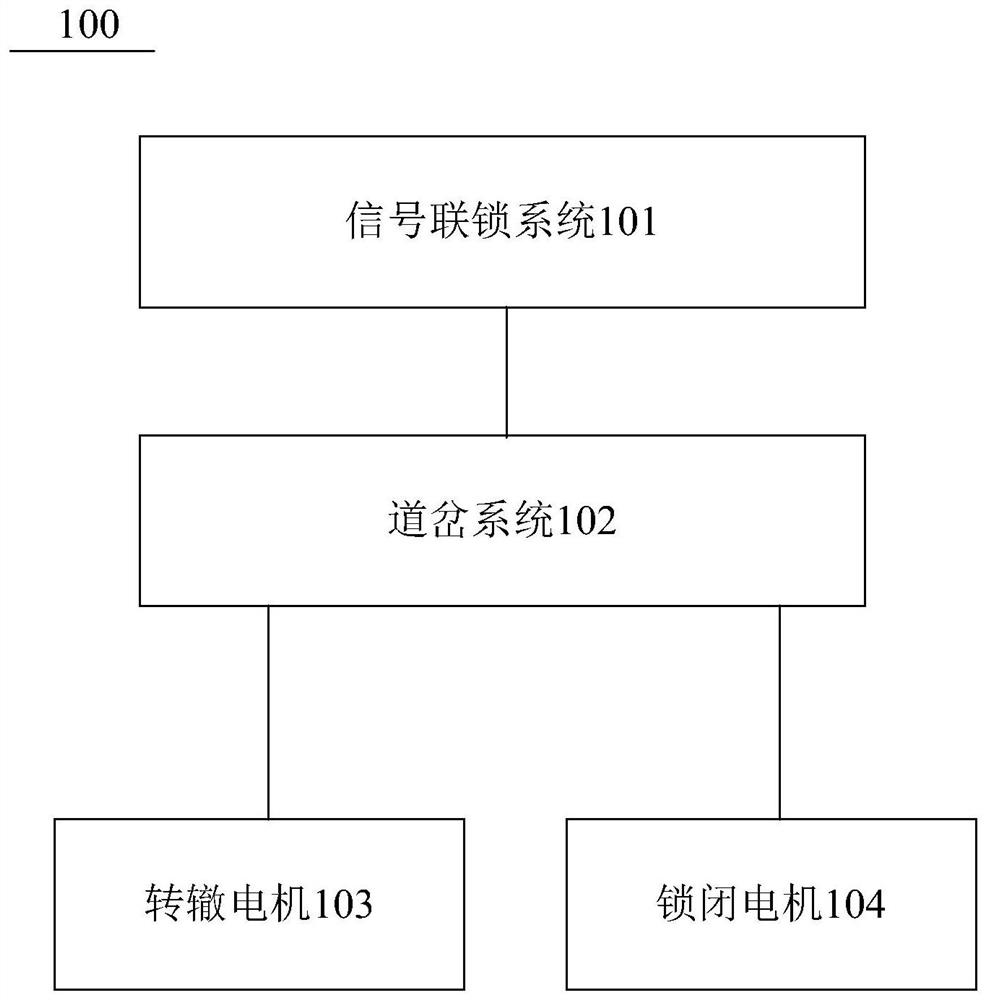
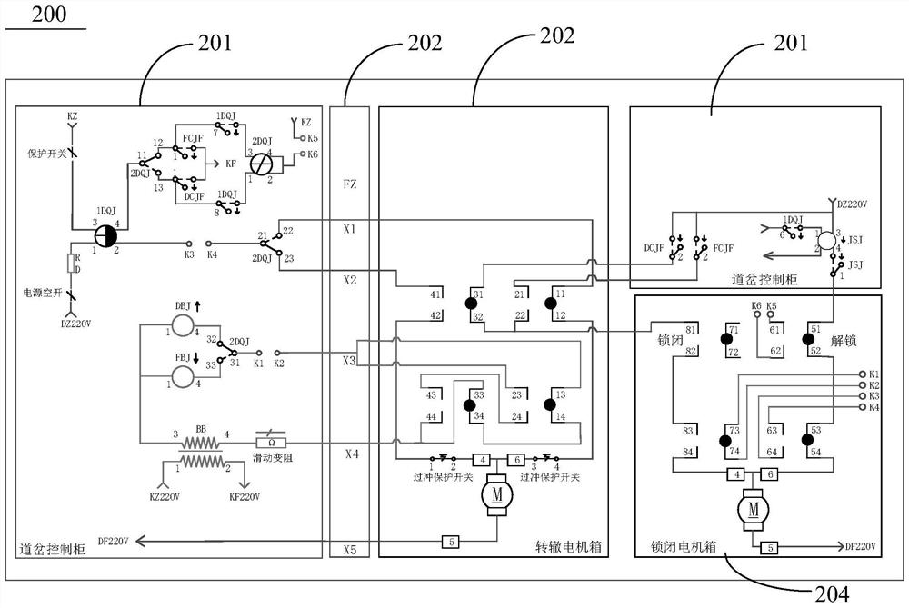
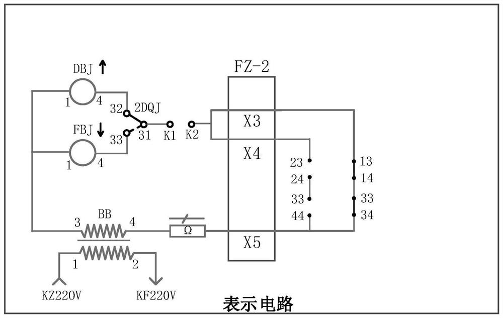
The present invention provides a turnout control circuit and a turnout control system. The turnout control circuit includes: a switch circuit, used to control the switch motor to complete the switch positioning and reverse position or reverse position de-positioning operation; a locking circuit, used to control the lock Turn off the motor to complete the unlocking or locking of the switch; the indicating circuit is used to generate a signal indicating the position of the switch; and the automatic switch includes multiple rows of contacts, and each row of contacts is respectively arranged on the switch circuit, the locking circuit and the indicating circuit. In one of them, the automatic switch is connected with the switch, and controls the conduction of each row of contacts in response to the switch position and / or the locking state, so that the switch circuit, the locking circuit and the indicating circuit are connected or disconnect. The turnout control circuit and the turnout control system reduce the interactive nodes of each module circuit, make the control logic clearer and simpler, and use the automatic switch to replace the travel switch, which reduces the cost relative to the installation of the travel switch at each position.

Description

technical field [0001] The invention relates to the technical field of turnout switching control, in particular to a turnout control circuit and a turnout control system. Background technique [0002] With the increasing demand for rail transit in major cities, rail transit systems such as subways, light rails, straddle monorails, and rubber-tyred trams have gradually appeared in the public's field of vision and become the preferred means of transportation for travel. Among them, the medium and low-volume traffic systems such as straddle monorail and rubber-tyred tram have the advantages of low cost, short construction period, and small footprint. The construction needs of various cities are increasing day by day. Different from traditional large railways and subways, the medium and low-volume transportation system pays more attention to the lightweight and intelligentization of system equipment. [0003] The turnout system is a line connection device that enables rolling s...

Claims


Application Information

Patent Timeline
Patent Type & Authority Patents(China)
IPC IPC(8): B61L5/06
CPCB61L5/06
Inventor 王有康
Owner BYD CO LTD
Learn More