
AI image recognition sensor probe-based edge compensation control system

A sensor probe and image recognition technology, which is applied in image communication, character and pattern recognition, TV system components, etc., can solve the problems that the motor driver cannot detect the accurate commutation signal, the positioning accuracy is not high enough, and the delay is high. The effect of friendly human-computer interaction, reducing the installation volume and improving the control accuracy

Inactive Publication Date: 2021-04-09
武汉茂格科技有限公司
View PDF6 Cites 0 Cited by
  • Summary
  • Abstract
  • Description
  • Claims
  • Application Information

AI Technical Summary

Problems solved by technology

It has the advantages of simple structure and convenient control, but the disadvantage is that the positioning accuracy is not high enough, and there may be a certain distance between the motor driver and the motor installation position during the user's on-site use, and in some places there are a large number of electrical equipment (such as frequency converters) There is generally strong electromagnetic interference in the field, so if the field wiring is unreasonable, the signal of the Hall switch position sensor that comes with the motor will be interfered, which will cause the motor driver to fail to detect the accurate commutation signal, thereby affecting to the normal operation of the motor
[0005] In addition, in order to further improve the effect of human-computer interaction, it is necessary to improve the input and output ports of the controller to avoid problems such as unstable signals, high delay, and single control mode.

Method used


Image

  • AI image recognition sensor probe-based edge compensation control system
  • AI image recognition sensor probe-based edge compensation control system

Examples


Embodiment Construction

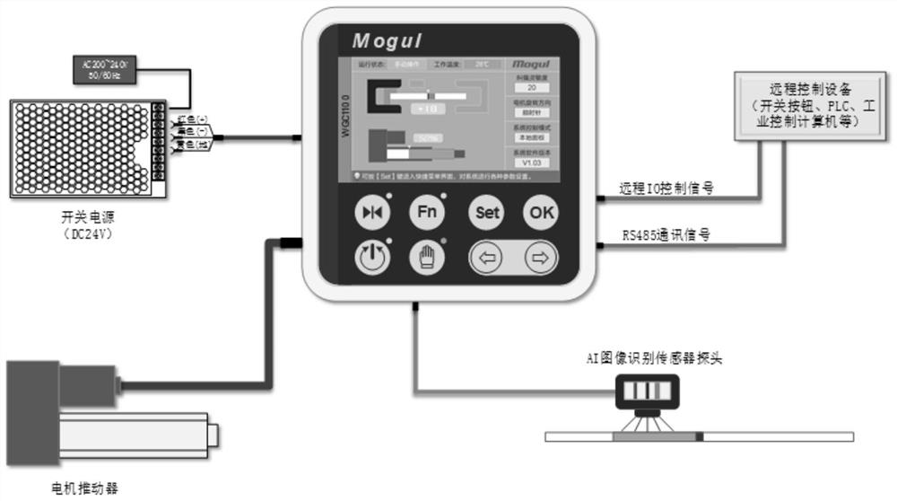
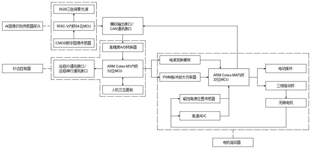
[0023] see Figures 1 to 2 , In the embodiment of the present invention, an AI-based image recognition sensor probe edge compensation control system includes an AI image recognition sensor probe, a motor driver and an edge compensation controller. The AI ​​image recognition sensor probe includes an image acquisition element, an RGB three-color background light source and RISC-V core 64-bit MCU, the output terminal of the image acquisition element is electrically connected to the input terminal of the RISC-V core 64-bit MCU, and the input terminal of the RGB three-color background light source is electrically connected to the output terminal of the RISC-V core 64-bit MCU. The motor driver includes an electric push rod and a drive board, the output end of the electric push rod is fixedly connected to the shell of the brushless motor, the drive board is integrally installed on the shell of the brushless motor, and the drive board includes a power conversion module, ARM cortex -M4...


PUM


Abstract

The invention relates to the technical field of automatic control, and discloses an AI image recognition sensor probe-based edge compensation control system, which comprises an AI image recognition sensor probe, a motor driver and an edge compensation controller, and is characterized in that the AI image recognition sensor probe comprises an image acquisition element, an RGB three-color background light source and an RISC-V kernel 64-bit MCU; and the motor driver comprises an electric push rod and a drive board. The drive board comprises a power conversion module, an ARM cortex-M4 kernel 32-bit MCU, a magnetic angle position sensor, a high-speed ADC and a three-phase drive axle composed of six power MOS tubes. The edge compensation controller comprises a man-machine interaction panel, a high-precision A / D converter, an ARM CotexM3 kernel 32-bit MCU, a PWM pulse amplification power device, a remote IO and a remote serial communication interface. The system is suitable for real-time detection of materials of various specifications and appearances, the positioning precision is greatly improved while signal interference is solved, and a friendly man-machine interaction effect is further provided.

Description

technical field [0001] The invention relates to the technical field of automatic control, in particular to an edge-filling control system for a sensor probe based on AI image recognition. Background technique [0002] In most of the existing automated production lines, in order to avoid material deviation in the transmission, transfer, processing and other links of materials, it is necessary to use an automatic edge-filling control system composed of sensor probes, driving mechanisms, supporting controllers and algorithms. Track, monitor and adjust the material's travel trajectory. [0003] In the existing automatic edge compensation control system, the commonly used displacement detection sensors generally include ultrasonic, infrared photoelectric and CCD image sensors. The image scanning detection element used by the CCD image sensor detection probe is a color or grayscale linear array CCD image sensor, but this linear array CCD image sensor can only track continuous and...

Claims


Application Information

Patent Timeline
Patent Type & Authority Applications(China)
IPC IPC(8): H04N5/225G06K9/00G06K9/20G06F3/044H02P6/08
CPCG06F3/044H02P6/08G06V20/00G06V10/141H04N23/56H04N23/54
Inventor 付春茂朱玉格
Owner 武汉茂格科技有限公司
Learn More