A tunnel blower for tunnel construction

A technology for tunnel construction and tunneling, which is applied to the components of pumping devices for elastic fluids, mechanical equipment, machines/engines, etc. It can solve problems such as gas flow resistance, polluted gas, and influence on the construction process, so as to improve work efficiency , reduce the amount of installation, reduce the effect of dust

Active Publication Date: 2021-07-09
JIANGSU VOCATIONAL INST OF ARCHITECTURAL TECH
View PDF16 Cites 0 Cited by
  • Summary
  • Abstract
  • Description
  • Claims
  • Application Information

AI Technical Summary

Problems solved by technology

[0002] When building a tunnel, since the tunnel is a relatively closed environment with only two ends connected to the outside world, and some tunnels are long, the exchange of gas in the tunnel with the outside world is very important; and excavation will generate a lot of dust during tunnel construction, and the dust will Floating in the gas, polluting the gas not only affects the normal construction process, but also has an adverse effect on the health of the excavators; traditional fans generally only rely on the rotation of the fan blades to blow the gas outward, because the motor is installed in the fan The middle position of the motor, and the rear end of the motor is flat, and then the rear end of the motor will cause a certain resistance to the gas flow, resulting in low working efficiency of the fan; and when the fan is installed now, it is generally hung on a fixed mounting frame. At the top of the tunnel, the parallelism of the fan cannot be adjusted (the fan works best when it is parallel to the tunnel), which reduces the ventilation effect of the fan, so we propose a tunnel fan for tunnel construction

Method used


Image

  • A tunnel blower for tunnel construction
  • A tunnel blower for tunnel construction
  • A tunnel blower for tunnel construction

Examples


Embodiment Construction

[0023] The following will clearly and completely describe the technical solutions in the embodiments of the present invention with reference to the accompanying drawings in the embodiments of the present invention. Obviously, the described embodiments are only some, not all, embodiments of the present invention. Based on the embodiments of the present invention, all other embodiments obtained by persons of ordinary skill in the art without making creative efforts belong to the protection scope of the present invention.

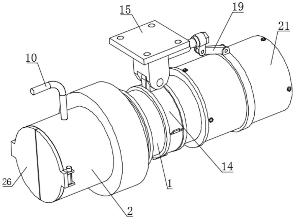
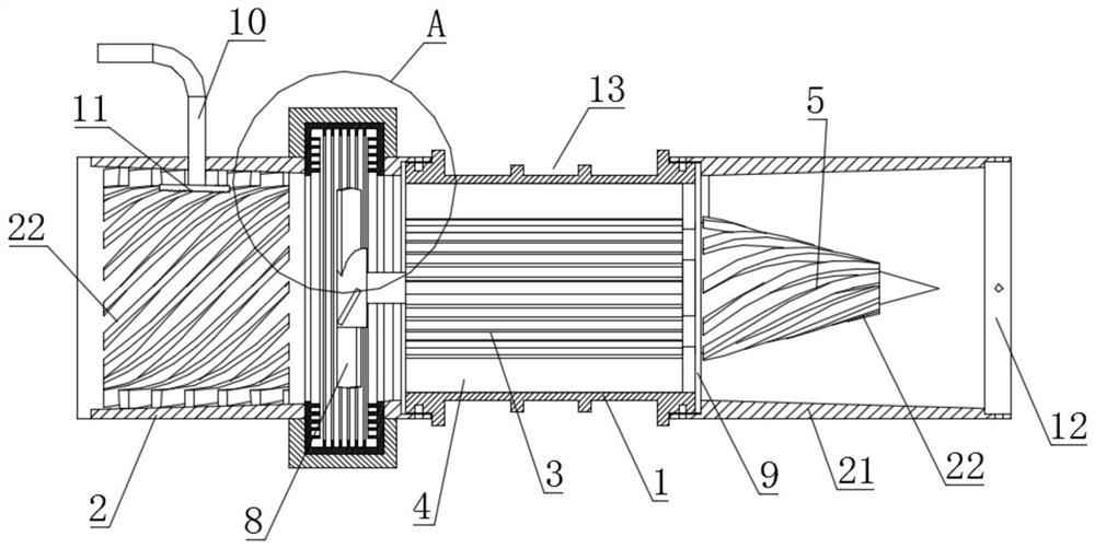
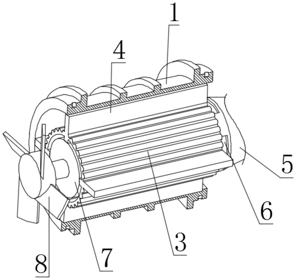
[0024] see Figure 1-9 , the present invention provides a technical solution: a tunnel fan for tunnel construction, including a base cylinder 1, the left and right ends of the base cylinder 1 are connected with an air guide pipe 2 and an air collection pipe 21 by bolts, The inner side walls of the air guide pipe 2 and the air collection pipe 21 are arranged on a conical slope, and the tapered slope of the inner side wall of the air collection pipe 21 is betwee...


PUM


Abstract

The invention discloses a tunnel fan used for tunnel construction, which comprises a base tube, the left and right ends of the base tube are movably connected with an air guiding pipe and an air collecting pipe, and the inner side walls of the air guiding pipe and the air collecting pipe are conical. The inner cylinder is sleeved with an inner cylinder, the outer wall of the inner cylinder is fixedly connected with a plurality of support plates, the right end of the inner cylinder is fixedly connected with a diversion cone, and the right end of the diversion cone runs through the dust cover And it extends to the inside of the air collecting pipe. There are multiple ventilation holes at the connection between the diversion cone and the inner cylinder. A motor is fixedly installed in the inner cylinder. A plurality of fan blades are fixedly connected to the output shaft of the motor, and the outer edge of the fan blade There is a sound-absorbing structure in a circle. According to the invention, after the gas enters the device, it will flow along the diversion cone, which reduces the resistance of the motor to the gas flow, and then makes the gas quickly flow between the base cylinder and the inner cylinder, and pass through the rotating diversion groove. Auxiliary to increase the pressure head and flow rate, improve the working efficiency of the device.

Description

technical field [0001] The invention relates to the technical field of tunnel ventilation, in particular to a tunnel fan used for tunnel construction. Background technique [0002] When building a tunnel, since the tunnel is a relatively closed environment with only two ends connected to the outside world, and some tunnels are long, the exchange of gas in the tunnel with the outside world is very important; and excavation will generate a lot of dust during tunnel construction, and the dust will Floating in the gas, polluting the gas not only affects the normal construction process, but also has an adverse effect on the health of the excavators; traditional fans generally only rely on the rotation of the fan blades to blow the gas outward, because the motor is installed in the fan The middle position of the motor, and the rear end of the motor is flat, and then the rear end of the motor will cause a certain resistance to the gas flow, resulting in low working efficiency of th...

Claims


Application Information

Patent Timeline
Patent Type & Authority Patents(China)
IPC IPC(8): E21F5/04F04D25/08F04D29/54
CPCE21F5/04F04D25/08F04D29/545
Inventor 苗磊刚
Owner JIANGSU VOCATIONAL INST OF ARCHITECTURAL TECH
Why Eureka
Try Eureka