
Nondestructive detector for strength of lightweight aggregate concrete

A lightweight aggregate concrete and detector technology, which is applied in the direction of strength characteristics, test material hardness, instruments, etc., can solve problems such as the deviation of the test angle of the rebound tester, the reduction of detection accuracy, and the complex structure of the strength nondestructive detector, so as to prevent detection The effect of simple error and reset adjustment methods

Active Publication Date: 2021-06-01
TONGJI UNIV ARCHITECTURAL DESIGN INST GRP CO LTD
View PDF9 Cites 1 Cited by
  • Summary
  • Abstract
  • Description
  • Claims
  • Application Information

AI Technical Summary

Problems solved by technology

(5) When the radius of the spherical surface at the top of the bullet is small, the energy absorbed by the concrete surface is large, the rebound value is low, and the detection accuracy is reduced. At the same time, it is easy to cause the deviation of the test angle when the hammer is used. When the concrete surface absorbs less energy
[0008] However, this strength non-destructive detector has a complex structure. When the position of the spring hammer needs to be reset, the buffer compression spring needs to be squeezed, and the spring spring must be stretched at the same time. It is laborious to reset the spring hammer. At the same time, the There is no device for temporarily fixing the pointer block on the non-destructive detector. When it is necessary to move to another place to observe the position of the pointer block, the position of the pointer block cannot be temporarily fixed, which will easily lead to errors in the data detected by the detector.

Method used


Image

  • Nondestructive detector for strength of lightweight aggregate concrete
  • Nondestructive detector for strength of lightweight aggregate concrete

Examples


Embodiment Construction

[0025] The following will clearly and completely describe the technical solutions in the embodiments of the present invention with reference to the accompanying drawings in the embodiments of the present invention. Obviously, the described embodiments are only some, not all, embodiments of the present invention.

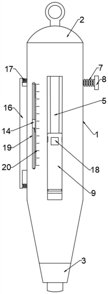
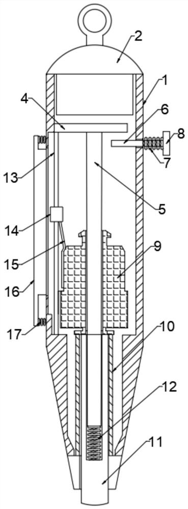
[0026] refer to Figure 1-Figure 2 , a non-destructive detector for the strength of lightweight aggregate concrete, comprising a casing 1, a detachable upper end plug 2 is installed on the top of the casing 1, a lower end plug 3 is installed on the bottom of the casing 1, and a fixed top outer wall of the casing 1 is installed Plate 4, a central guide rod 5 is installed on the bottom of the fixed plate 4, and the outer wall of the central guide rod 5 is slidably sleeved with a bullet hammer 9, and the outer wall of the bullet hammer 9 is fixedly connected with a bump 18, and the outer wall of the shell 1 A movable opening a corresponding to the bump 18 is provided, a...


PUM


Abstract

The invention discloses a lightweight aggregate concrete strength nondestructive detector, and belongs to the field of concrete quality detection. The lightweight aggregate concrete strength nondestructive detector comprises a shell, a detachable upper end plug is installed at the top of the shell, a lower end plug is installed at the bottom of the shell, a fixing plate is installed on the outer side wall of the top of the shell, and a center guide rod is installed at the bottom of the fixing plate; the outer side wall of the center guide rod is slidably sleeved with an elastic hammer, the outer side wall of the elastic hammer is fixedly connected with a protruding block, and the outer side wall of the shell is provided with a movable opening a corresponding to the protruding block. According to the invention, the outer side wall of the shell is provided with a T-shaped limiting block and a limiting spring a, when a pointer block reaches a certain position, the T-shaped limiting block is pressed towards the direction of the shell, so that the T-shaped limiting block can be pressed into the shell, the pointer block is limited, and the situation that the position of the pointer block cannot be fixed when the pointer block is moved to other places to observe the position of the pointer block is avoided; and detection errors are prevented.

Description

technical field [0001] The invention relates to the field of concrete quality detection, in particular to a non-destructive detector for the strength of lightweight aggregate concrete. Background technique [0002] As we all know, the strength and quality of concrete is related to the overall safety and service life of the building structure. Therefore, it is particularly important to do a good job in the quality control, quality supervision and quality inspection of concrete during the entire life cycle of the building. The rebound method is widely used in construction projects because of its simple operation, convenient use, economy, rapidity and considerable detection accuracy. [0003] In recent years, lightweight aggregate concrete has been widely used in various fields of construction engineering because of its light weight, high strength, good thermal insulation effect, excellent fire resistance and durability. At present, lightweight aggregate concrete has become an...

Claims


Application Information

Patent Timeline
Patent Type & Authority Applications(China)
IPC IPC(8): G01N3/02G01N3/06G01N3/52
CPCG01N3/02G01N3/062G01N3/52G01N2203/0083G01N2203/0605
Inventor 陈殿翔
Owner TONGJI UNIV ARCHITECTURAL DESIGN INST GRP CO LTD
Learn More