
Bill issuing box and bill issuing device

A bill and bill wheel technology, which is applied in the field of bill issuance, can solve the problems of wrinkled cards, bad bills, etc., and achieve the effect of reducing the probability of double sheets and bill folds.

Pending Publication Date: 2021-06-01
GRG BAKING EQUIP CO LTD
View PDF0 Cites 1 Cited by
  • Summary
  • Abstract
  • Description
  • Claims
  • Application Information

AI Technical Summary

Problems solved by technology

During the working process of the traditional bill distribution box, the stored bills are transported outward one by one under the drive of the ticket sorting wheel and the floating wheel that is in contact with the ticket sorting wheel, so that the bills can be smoothly output out of the bill distribution box in sequence , when one of the tickets just breaks away from the ticket sorting wheel and the floating wheel, the next note behind one of the notes will continue to move forward and touch the floating wheel, and the floating wheel can prevent the output of the next note, however When the material of the bill is soft, the next bill will wrinkle when it comes into contact with the floating wheel, resulting in the bad phenomenon of jamming

Method used


Image

  • Bill issuing box and bill issuing device
  • Bill issuing box and bill issuing device
  • Bill issuing box and bill issuing device

Examples


Embodiment Construction

[0032] In order to make the above objects, features and advantages of the present invention more comprehensible, specific implementations of the present invention will be described in detail below in conjunction with the accompanying drawings. In the following description, numerous specific details are set forth in order to provide a thorough understanding of the present invention. However, the present invention can be implemented in many other ways different from those described here, and those skilled in the art can make similar improvements without departing from the connotation of the present invention, so the present invention is not limited by the specific embodiments disclosed below.

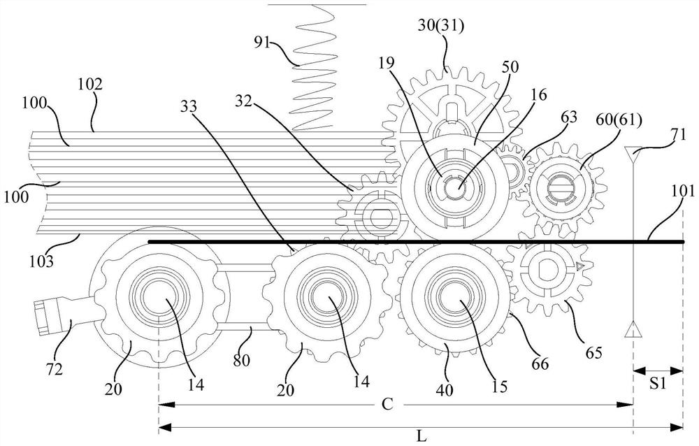
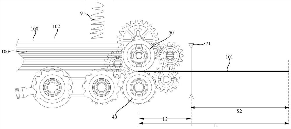
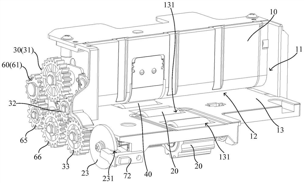
[0033] refer to figure 1 , image 3 and Figure 4 , figure 1 It shows a schematic diagram of the state in which the bottommost ticket 101 in the ticket distribution box is about to leave the ticket collection wheel 20 according to an embodiment of the present invention, image 3 It sh...


PUM


Abstract

The invention relates to a bill issuing box and a bill issuing device. The bill issuing box comprises a box body, a bill taking wheel, a first driving assembly, a bill distributing wheel, a reversing wheel, a second driving assembly, a first sensor and a controller. The box body is provided with a ticket storage chamber, and the side wall of the bottom of the ticket storage chamber is provided with a ticket outlet. The bill taking wheel is rotatably arranged on the bottom wall of the bill storage chamber, and the bill taking wheel is used for making contact with the bottommost bill in the bills stacked in the bill storage chamber and driving the bottommost ticket to move outwards through the bill outlet. The contact part of the wheel surface of the bill separating wheel and the wheel surface of the reversing wheel is opposite to the bill outlet; and the bill separating wheel is used for driving the bottommost bill to move outwards through the bill outlet. When the bill separating wheel drives the bottommost bill to move away from the bill taking wheel, the controller controls the first driving assembly to stop driving the bill taking wheel, the bill taking wheel stops rotating, and the bad phenomenon that the last but one bill is driven to move towards the bill outlet and makes contact with the reversing wheel to cause wrinkles is avoided. The probability of overlapping, connecting and bill wrinkling can be greatly reduced.

Description

technical field [0001] The invention relates to the technical field of ticket distribution, in particular to a ticket distribution box and a ticket distribution device. Background technique [0002] With the rapid development of science and technology, more and more enterprises and institutions hope to improve their related business handling capabilities with the help of automated bill issuing devices. The bill issuing device mainly outputs the stored bills and uses the printing module to print relevant data on the output bills, and the bills after printing the data are given to the user. A traditional bill issuing device includes a bill issuing box for storing bills. During the working process of the traditional bill distribution box, the stored bills are transported outward one by one under the drive of the ticket sorting wheel and the floating wheel that is in contact with the ticket sorting wheel, so that the bills can be smoothly output out of the bill distribution box...

Claims


Application Information

Patent Timeline
Patent Type & Authority Applications(China)
IPC IPC(8): G07F17/26
CPCG07F17/26
Inventor 谭栋蒋壮吴志刚
Owner GRG BAKING EQUIP CO LTD
Learn More