
A power distribution cabinet with good airtightness

A sealed, power distribution cabinet technology, applied in substation/distribution device enclosures, electrical components, door/window accessories, etc., can solve problems such as rainwater ingress, and achieve the effect of reducing gaps, good sealing, and increasing stability

Active Publication Date: 2022-04-19
山东鲁通机电设备有限公司
View PDF0 Cites 0 Cited by
  • Summary
  • Abstract
  • Description
  • Claims
  • Application Information

AI Technical Summary

Problems solved by technology

[0004] The technical problem to be solved by the present invention is to provide a power distribution cabinet with good airtightness, one of the purposes is to improve the airtightness between the cabinet door and the cabinet body, and solve the gap between the cabinet door and the cabinet body It is easy to cause the problem of rainwater entering; another purpose is to solve the problem of greater friction between the cabinet door and the cabinet body caused by excessive force when closing the cabinet door, so as to reduce the distance between the cabinet door and the cabinet body when closing the cabinet door. friction effect between

Method used


Image

  • A power distribution cabinet with good airtightness
  • A power distribution cabinet with good airtightness
  • A power distribution cabinet with good airtightness

Examples


Embodiment 1

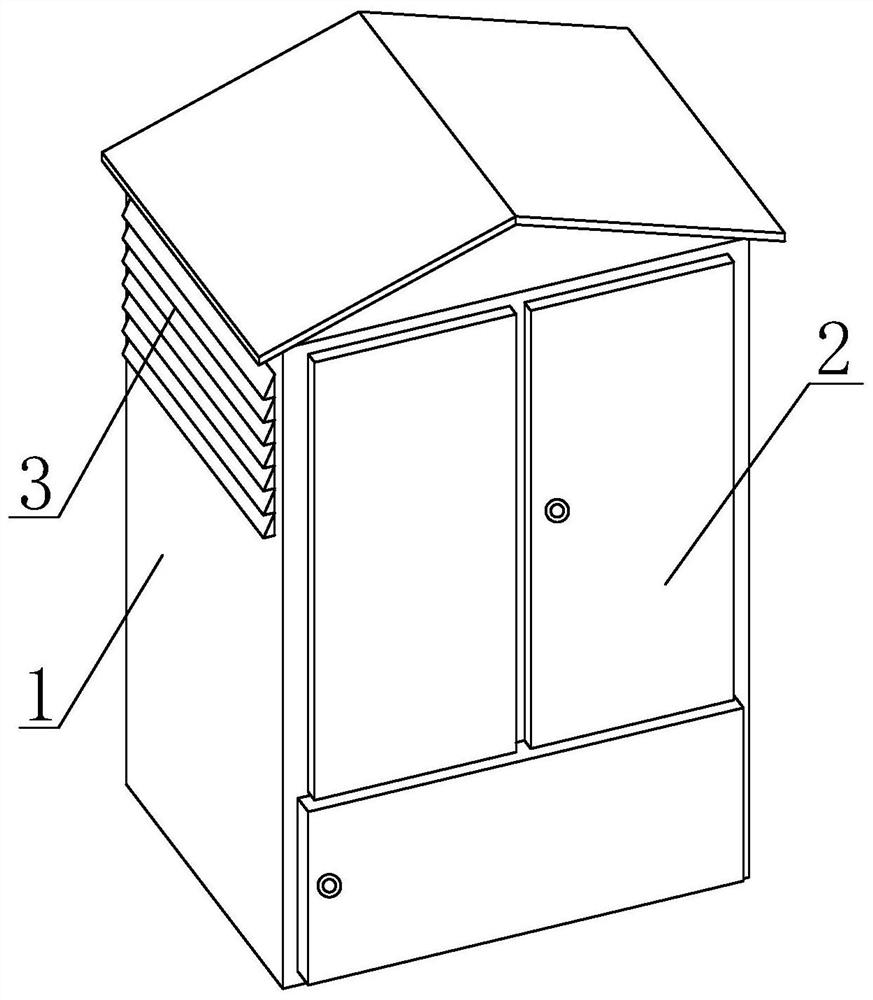
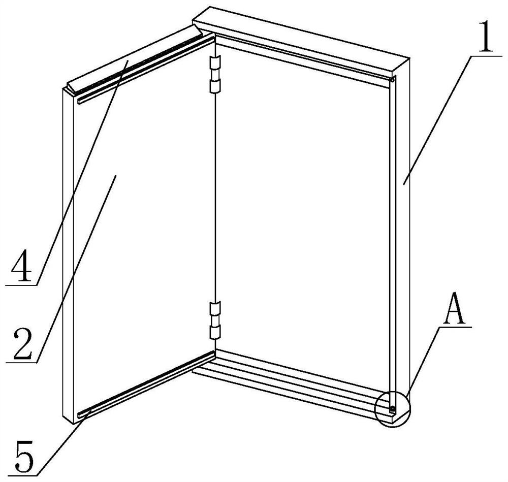
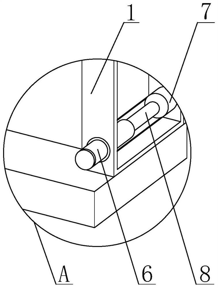
[0030] Such as Figure 1-Figure 8 As shown, the present invention provides a power distribution cabinet with good airtightness, including a cabinet body 1 and a cabinet door 2, one end of the cabinet door 2 is rotatably connected to the outer wall of the cabinet body 1, and heat dissipation windows are provided on both sides of the cabinet body 1 3. The top of the cabinet door 2 is provided with a sealing device 4, and the sealing device 4 is located symmetrically at the upper and lower ends of the cabinet door 2. The inner wall of the cabinet door 2 is fixed with a magnetic suction strip 5, and the bottom of the cabinet body 1 is provided with a connection Block 7, the two ends of the connection block 7 are embedded and connected with the inner wall of the cabinet body 1, the inner wall of the connection block 7 is welded with an elastic member 8, and one end of the elastic member 8 is fixedly connected with a top column 6, and the outer wall of the top column 6 is connected t...

Embodiment 2

[0033] Such as figure 2 , Figure 4 As shown, on the basis of Embodiment 1, the present invention provides a technical solution: the sealing device 4 includes a supporting plate 41, a fixed block 42 and a bottom plate 43, the outer wall of the supporting plate 41 is embedded and connected with the inner wall of the fixed block 42, and the fixed block 42 outer wall is provided with through hole 44, and the inwall of through hole 44 is lapped with water pipe one 12, and the outer wall of water pipe one 12 is lapped with the inwall of running water tank 13, and the through hole 44 that offers is in order to pass between supporting plate 41 and fixed block 42. The remaining gaps flow into the inside of the sealing device 4 for drainage, so that the rainwater flows out to the outside of the sealing device 4 through the water pipe 12, and the inclined plate 43 provided has a certain slope, so that the rainwater entering the inside of the sealing device 4 can flow to the outside of ...

Embodiment 3

[0035] Such as Figure 4-5 As shown, on the basis of Embodiment 1 and Embodiment 2, the present invention provides a technical solution: preferably, the inner walls of the first block 46 and the second block 47 are provided with limiting grooves, and the limiting grooves The inner side wall is slidably connected with a connecting pipe 10, and the outer wall of the connecting pipe 10 is slidably connected with a buffer spring 11. The bottom of the buffer spring 11 is overlapped with a third block 9, and the bottom of the third block 9 is connected to the top of the first block 46. Fixedly connected, and the third block 9 is located symmetrically at the upper and lower ends of the buffer spring 11, when the angle between the first block 46 and the second block 47 changes, the connecting pipe 10 will slide into the limit groove Inside, through the cooperation of the connecting pipe 10 and the limit groove, it is possible to prevent excessive deviation of the rotation angles of th...


PUM


Abstract

The invention discloses a power distribution cabinet with good airtightness, which relates to the technical field of power distribution cabinets and comprises a cabinet body and a cabinet door. One end of the cabinet door is rotatably connected to the outer wall of the cabinet body. There is a heat dissipation window, the top of the cabinet door is provided with a sealing device, and the sealing device is arranged symmetrically at the upper and lower ends of the cabinet door, the inner side wall of the cabinet door is fixedly installed with magnetic suction strips, and the bottom of the cabinet body is provided with A connection block, the two ends of the connection block are embedded and connected with the inner wall of the cabinet body, and the inner wall of the connection block is welded with elastic parts. The present invention reduces the gap between the cabinet door and the cabinet body through the cooperation of the sealing device and the cabinet door, and solves the problem that rainwater easily enters the inside of the cabinet body in rainy days and causes potential safety hazards. The cooperation of the water pipe two can flow the rainwater remaining on the cabinet door into the inside of the water pipe two, which facilitates the discharge of the rainwater and reduces the possibility of the rainwater entering the inside of the cabinet.

Description

technical field [0001] The invention relates to the technical field of power distribution cabinets, in particular to a power distribution cabinet with good airtightness. Background technique [0002] The power distribution cabinet is divided into power distribution cabinet, lighting distribution cabinet and metering cabinet. It is the final equipment of the power distribution system. The power distribution cabinet is the general name of the motor control center. , the motor control center is used in occasions where the load is concentrated and there are many circuits. It is widely used in power plants, substations, enterprises and other power users. ensure. [0003] At present, the power distribution cabinets are generally installed outdoors. In rainy weather, rainwater easily enters the interior of the power distribution cabinets. Although the power distribution cabinets on the market have certain waterproof capabilities, the gap between the cabinet door and the power dist...

Claims


Application Information

Patent Timeline
Patent Type & Authority Patents(China)
IPC IPC(8): H02B1/28H02B1/30E05F5/08
CPCH02B1/28H02B1/30H02B1/306E05F5/08E05Y2900/60
Inventor 马驰
Owner 山东鲁通机电设备有限公司
Learn More