
Textile waste collecting device for textile production of chemical fabric

A technology of textile waste and collection device, which is applied in the direction of combination device, chemical instrument and method, cleaning method using gas flow, etc. problem, to achieve the effect of convenient secondary recycling, easy removal, convenient cleaning and cleaning

Pending Publication Date: 2021-06-04
莫晨良
View PDF8 Cites 0 Cited by
  • Summary
  • Abstract
  • Description
  • Claims
  • Application Information

AI Technical Summary

Benefits of technology

This patented technology allows for easy removal or disposal of used fabric items such as clothing during manufacturing processes without causing environmental concerns due to their production process's wastes being collected at different locations throughout the world. By passing them into an enclosed space called a specialized container with multiple layers of filtering material attached on top it, these fabrics will fall down onto specific areas where they may cause problems if left untreated over time.

Problems solved by technology

This patented technical problem addressed by this patents relates to improving the recycling process for disposable garments made up mainly of synthetic fibers such as polyester or other plastic material that have been used widely throughout industry over time due to their durability and ease of manufacturing processes compared to natural fiber fabrics like cotton yarn. Current methods involve manual sorting of these wasted clothes into different types based on its properties (like weight) before they go through various stages of cleaning/recycling steps.

Method used

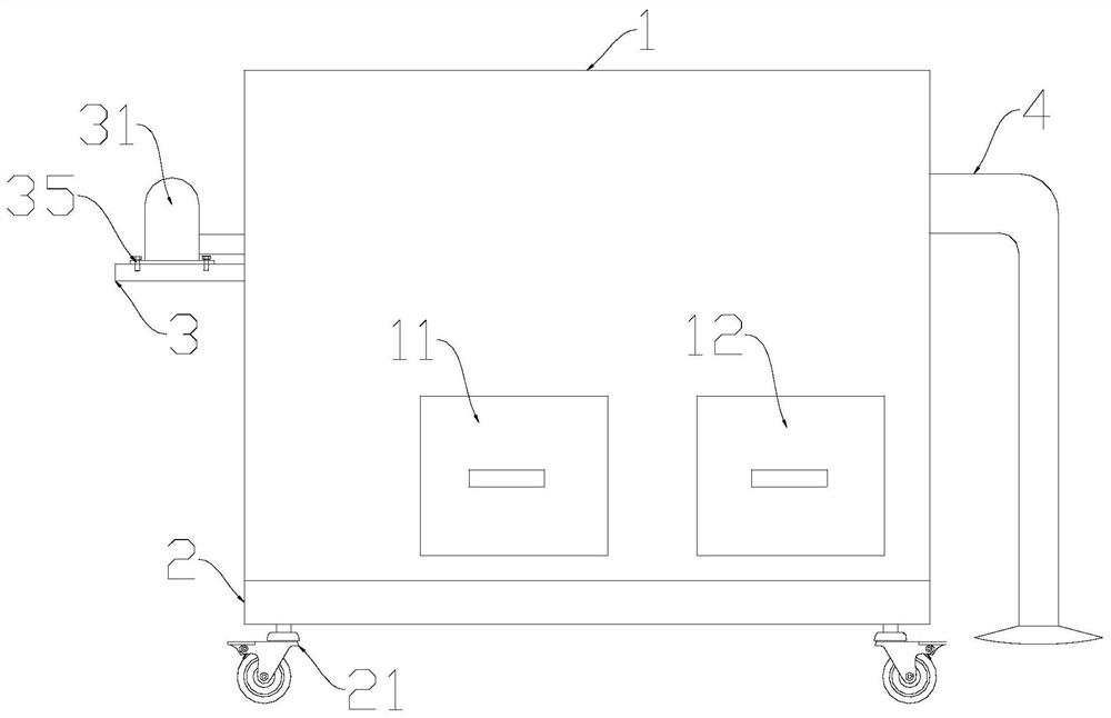

Image

  • Textile waste collecting device for textile production of chemical fabric
  • Textile waste collecting device for textile production of chemical fabric
  • Textile waste collecting device for textile production of chemical fabric

Examples


Embodiment

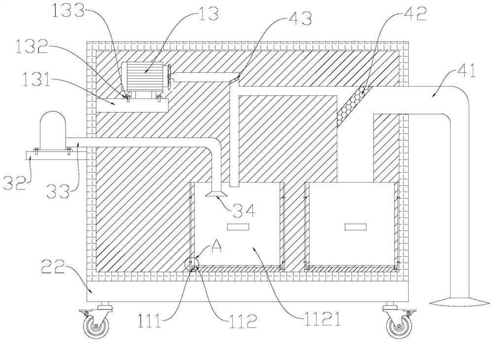
[0025] see Figure 1-3 , in the illustration: this embodiment is a preferred implementation of this technical solution, a textile waste collection device for textile production of chemical fiber cloth, including a housing 1, a moving device 2, a spraying device 3 and a dust collection device 4; The lower end of the housing 1 is provided with a mobile device 2, the mobile device 2 is welded and fixed to the lower surface of the housing 1, and the right outer end of the housing 1 is provided with a spraying device 3, and the spraying device 3 is connected to the housing 1. The right outer end is fixedly connected, the left outer end of the housing 1 is provided with a dust suction device 4, and the dust suction device 4 is fixedly connected to the left outer end of the housing 1;

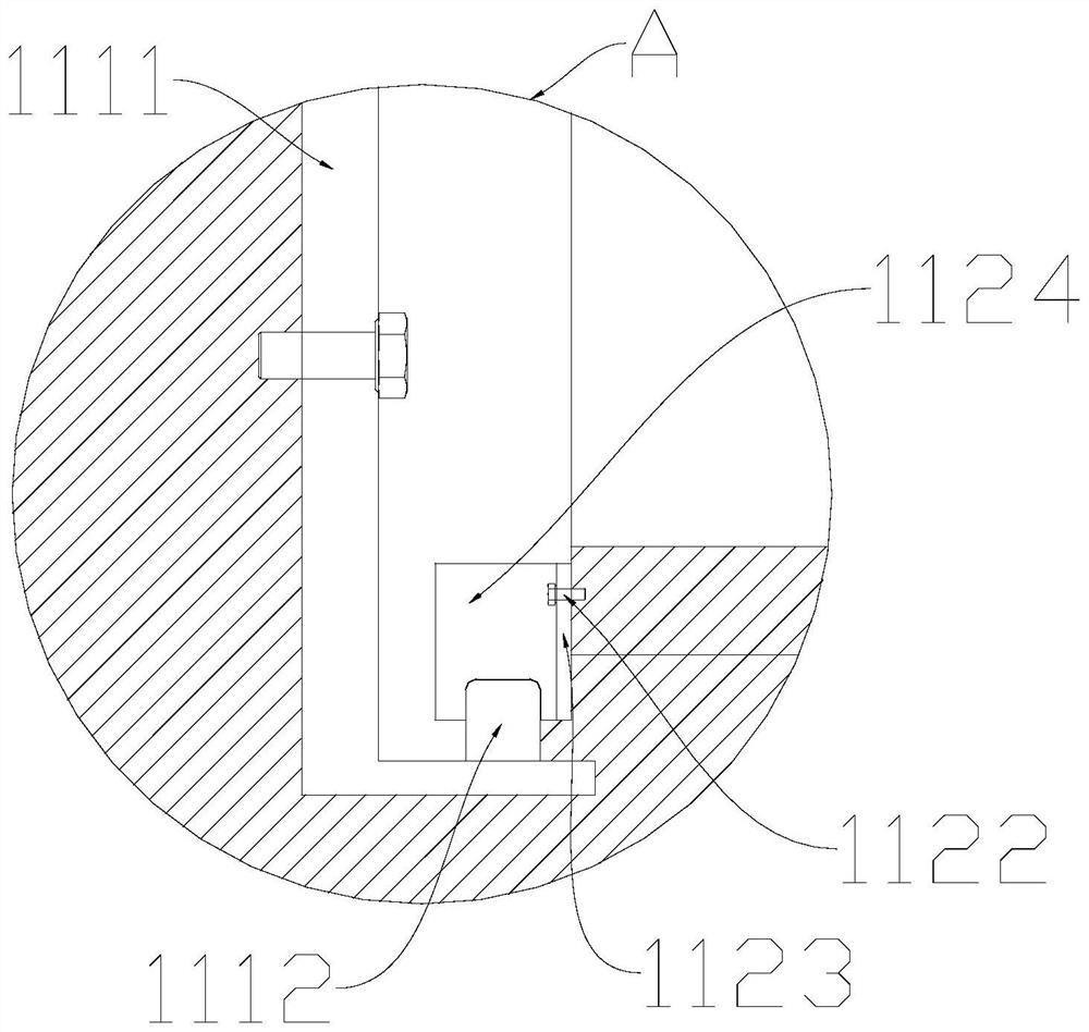
[0026] Such as figure 2 As shown, the housing 1 includes a dust collection device 11, a textile waste collection mechanism 12, and a dust collection motor assembly 13. A dust collection device 11 is...


PUM


Abstract

The invention relates to the technical field of textile machinery, in particular to a textile waste collecting device for textile production of chemical fabric. The textile waste collecting device comprises a shell, a moving device, a spraying device and a dust suction device, wherein the lower end of the shell is fixedly welded to the moving device, the spraying device is fixedly connected to the outer end of the right side of the shell, and the dust suction device is fixedly connected to the outer end of the left side of the shell. The textile waste collecting device is pushed to a designated position through a universal wheel assembly, then a dust suction motor assembly is turned on, and textile waste enters the shell through a dust suction pipe; the textile waste falls into a waste collecting mechanism through a coarse filter screen, and dust particles fall into a dust collecting device through a fine filter screen; when the textile waste is collected to a certain degree, an operator can easily take out a collecting box through sliding connection between a guide rail and a sliding block; and thus, cleaning, sweeping and secondary recycling are very convenient.

Description


Claims


Application Information

Patent Timeline
Owner 莫晨良
Learn More